ArduiNIX: 8 x Nixie Tubes
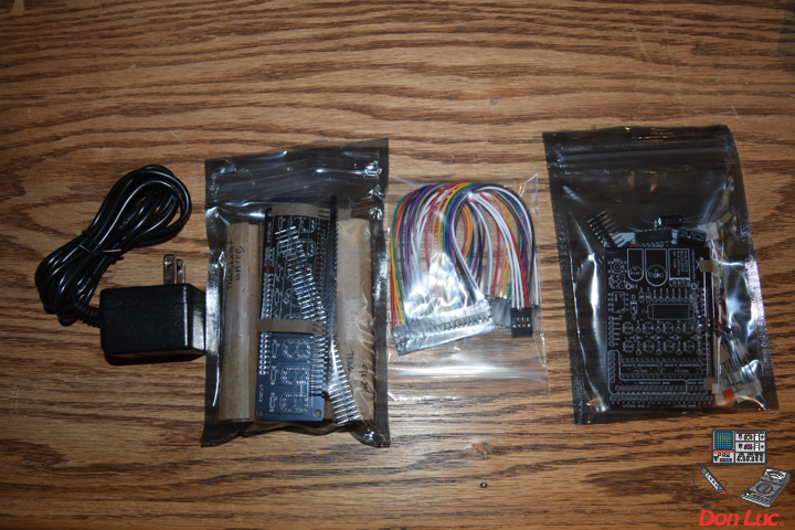
The ArduiNIX shield is a user programmable platform for driving multiplexed Nixie tube or other high voltage displays.
The ArduiNIX shield uses digital data pins 2,3,4,5,6,7,8,9,10,11,12,13 on the Arduino.
AREF, IOREF, TX(digital 1), RX(digital 0), Analog 0-5, digital 18 and 19 are free to use as inputs/outputs.
An explanation of how the Arduinix works:
The ArduiNIX works by listening to a signal from the Arduino to tell it when to switch on one of the four anode pins., and when to switch on any single or combination of cathode channels in the two sets of 10 cathode sets that are controlled by the nixie tube driver chips.
The Anode pins go hot, send 180 volts to the nixie tube anode connection, and the system waits for the code to tell the arduinix to ground out one of the cathode pins that are controlled by the twoDriver ICs.
Once the Arduino code tells the ArduiNIX to open an anode channel, which is connected to the anode pin of your tube, and the code tells the ArduiNIX to ground out a cathode channel, 180 volts flow into the nixie tube, lighting the element that is connected to the cathode channel.
When multiplexing, you have one anode channel connected to two nixie tubes, and one set of nixie cathodes per cathode channels on the ArduiNIX. Doing so allows you to drive up to 8 ten element nixie tubes, pairs of tubes sharing anodes, alternating cathode grounds at a fast enough rate that we don’t see a flicker.
The ArduiNIX is 4×20 Multiplexed,meaning there are a total of 4 anodes and 20 cathodes that can be multiplexed and controlled through the code. This means that up to 80 signals can be controlled. Either eight 10 numeral tubes or 80 Neon bulbs like the INS-1. Or any combination of numeric tubes and dots.
The ArduiNIX V3 features Analog 0-5, GND, Reset, SCL, SDA, AREF, 5V, TX and RX broken out to an input/output section of headers at the front of the board near the cathode bank.
Don Luc

