RTOS
Project #24 – RTOS – Bluetooth – Mk03
——
#DonLucElectronics #DonLuc #ESP32 #RTOS #FreeRTOS #Bluetooth #ThumbJoystick #Keyboard #Arduino #Project #Fritzing #Programming #Electronics #Microcontrollers #Consultant
——
——
——
——
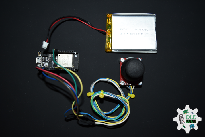
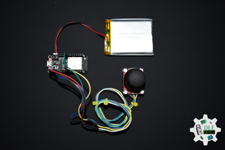
Joystick
A joystick is an input device consisting of a stick that pivots on a base and reports its angle or direction to the device it is controlling. Joysticks are often used to control video games, and usually have one or more push-buttons whose state can also be read by the computer. A popular variation of the joystick used on modern video game consoles is the analog stick. Joysticks are also used for controlling machines such as cranes, trucks, underwater unmanned vehicles, wheelchairs, surveillance cameras, and zero turning radius lawn mowers. This is a joystick very similar to the analog joysticks on PS2 controllers. Directional movements are simply two potentiometers, one for each axis. Pots are 10k Ohm each. This joystick also has a select button that is actuated when the joystick is pressed down.
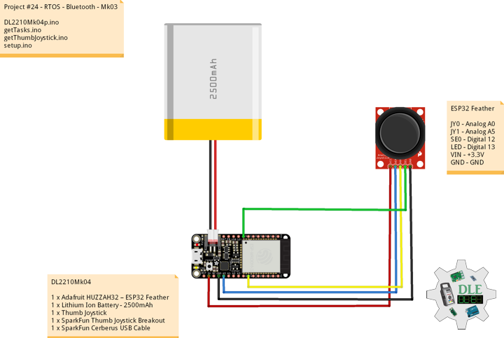
DL2210Mk04
1 x Adafruit HUZZAH32 – ESP32 Feather
1 x Lithium Ion Battery – 2500mAh
1 x Thumb Joystick
1 x SparkFun Thumb Joystick Breakout
1 x SparkFun Cerberus USB Cable
ESP32 Feather
JY0 – Analog A0
JY1 – Analog A5
SE0 – Digital 12
LED – Digital 13
VIN – +3.3V
GND – GND
——
DL2210Mk04p.ino
/* ***** Don Luc Electronics © ***** Software Version Information Project #24 - RTOS - Bluetooth - Mk03 24-03 DL2210Mk04p.ino 1 x Adafruit HUZZAH32 – ESP32 Feather 1 x Lithium Ion Battery - 2500mAh 1 x Thumb Joystick 1 x SparkFun Thumb Joystick Breakout 1 x SparkFun Cerberus USB Cable */ // Include the Library Code // FreeRTOS ESP32 #if CONFIG_FREERTOS_UNICORE #define ARDUINO_RUNNING_CORE 0 #else #define ARDUINO_RUNNING_CORE 1 #endif // ESP32 BLE Keyboard #include <BleKeyboard.h> // ESP32 BLE Keyboard BleKeyboard bleKeyboard; // Connections to joystick // Vertical const int VERT = A0; // Horizontal const int HORIZ = A5; // Pushbutton const int SEL = 12; // Initialize variables for analog and digital values int vertical; int horizontal; int selec; // Led Built In #ifndef LED_BUILTIN #define LED_BUILTIN 13 #endif // Define two tasks for Blink void isTaskBlink( void *pvParameters ); // Software Version Information String sver = "24-03"; void loop() { // ESP32 BLE Keyboard if(bleKeyboard.isConnected()) { // Thumb Joystick isThumbJoystick(); } // Delay delay( 1000 ); }
getTasks.ino
// Tasks // Setup Task void isSetupTask(){ // Now set up two tasks to run independently // TaskBlink xTaskCreatePinnedToCore( isTaskBlink , "TaskBlink" // A name just for humans , 1024 // This stack size can be checked & adjusted by reading. , NULL , 2 // Priority, with 2 being the highest, and 0 being the lowest. , NULL , ARDUINO_RUNNING_CORE); // Now the task scheduler, which takes over control of scheduling individual tasks, // is automatically started. } // This is a Task Blink void isTaskBlink(void *pvParameters) { (void) pvParameters; // Blink // Turns on an LED on for 2 second, then off for 2 second, repeatedly // Initialize digital LED_BUILTIN on pin 13 as an output. pinMode(LED_BUILTIN, OUTPUT); // A Task shall never return or exit for (;;) { // Turn the LED on (HIGH is the voltage level) digitalWrite(LED_BUILTIN, HIGH); // One tick delay in between reads vTaskDelay(2000); // Turn the LED off by making the voltage LOW digitalWrite(LED_BUILTIN, LOW); // One tick delay in between reads vTaskDelay(2000); } }
getThumbJoystick.ino
// Thumb Joystick void isThumbJoystick() { // Read all values from the joystick // Joystick was sitting around 2047 for the vertical and horizontal values // Will be 0-4095 // Vertical vertical = analogRead(VERT); if (vertical == 4095) { // Volume Up bleKeyboard.write(KEY_MEDIA_VOLUME_UP); } else if (vertical == 0) { // Volume Down bleKeyboard.write(KEY_MEDIA_VOLUME_DOWN); } // Horizontal // Will be 0-4095 horizontal = analogRead(HORIZ); if (horizontal == 4095) { // Previous Track bleKeyboard.write(KEY_MEDIA_PREVIOUS_TRACK); } else if (horizontal == 0) { // Next Track bleKeyboard.write(KEY_MEDIA_NEXT_TRACK); } // Will be HIGH (1) if not pressed, and LOW (0) if pressed selec = digitalRead(SEL); if (selec == 0) { // Play/Pause media key bleKeyboard.write(KEY_MEDIA_PLAY_PAUSE); } }
setup.ino
// Setup void setup() { // Make the SEL line an input pinMode(SEL, INPUT_PULLUP); // ESP32 BLE Keyboard bleKeyboard.begin(); // Setup Task isSetupTask(); }
——
People can contact us: https://www.donluc.com/?page_id=1927
Technology Experience
- Single-Board Microcontrollers (PIC, Arduino, Raspberry Pi,Espressif, etc…)
- IoT
- Wireless (Radio Frequency, Bluetooth, WiFi, Etc…)
- Robotics
- Camera and Video Capture Receiver Stationary, Wheel/Tank and Underwater Vehicle
- Unmanned Vehicles Terrestrial and Marine
- Machine Learning
- RTOS
- Research & Development (R & D)
Instructor and E-Mentor
- IoT
- PIC Microcontrollers
- Arduino
- Raspberry Pi
- Espressif
- Robotics
Follow Us
J. Luc Paquin – Curriculum Vitae – 2022 English & Español
https://www.jlpconsultants.com/luc/
Web: https://www.donluc.com/
Web: https://www.jlpconsultants.com/
Facebook: https://www.facebook.com/neosteam.labs.9/
YouTube: https://www.youtube.com/channel/UC5eRjrGn1CqkkGfZy0jxEdA
Twitter: https://twitter.com/labs_steam
Pinterest: https://www.pinterest.com/NeoSteamLabs/
Instagram: https://www.instagram.com/neosteamlabs/
Don Luc
Project #24 – RTOS – Magnetometers HMC5883L – Mk02
——
#DonLucElectronics #DonLuc #SparkFunRedBoard #RTOS #FreeRTOS #Magnetometer #Arduino #Project #Fritzing #Programming #Electronics #Microcontrollers #Consultant
——
——
——
——
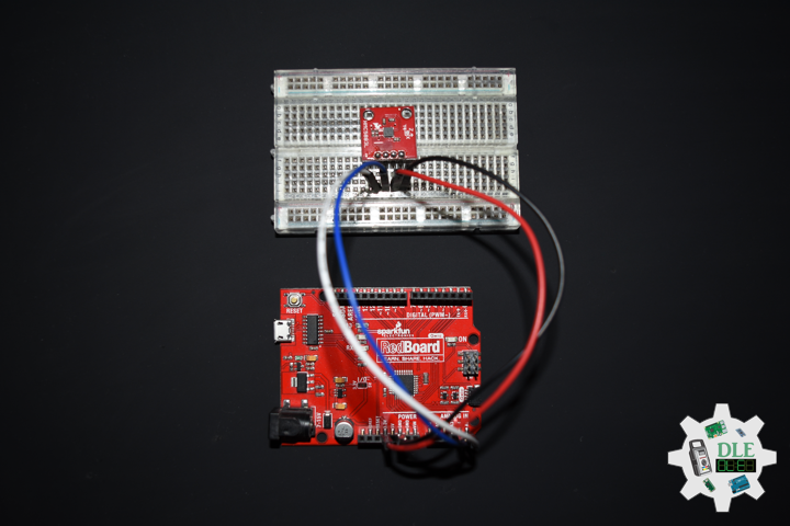
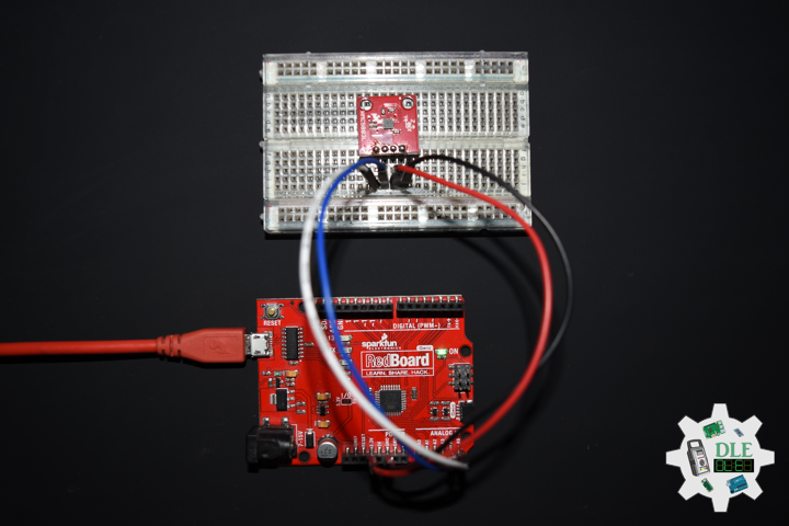
SparkFun Triple Axis Magnetometer Breakout – HMC5883L
This is a breakout board for Honeywell’s HMC5883L, a 3-axis digital compass. Communication with the HMC5883L is simple and all done through an I2C interface. There is no on-board regulator, so a regulated voltage of 2.16-3.6VDC should be supplied. The breakout board includes the HMC5883L sensor and all filtering capacitors as shown. The power and 2-wire interface pins are all broken out to a 0.1″ pitch header.
Magnetometers have a wide range of uses. The most common include using the chip as a digital compass to sense direction or using them to detect ferrous (magnetic) metals. Magnetic fields and current go hand-in-hand. When current flows through a wire, a magnetic field is created. This is the basic principle behind electromagnets. This is also the principle used to measure magnetic fields with a magnetometer. The direction of Earth’s magnetic fields affects the flow of electrons in the sensor, and those changes in current can be measured and calculated to derive a compass heading or other useful information.
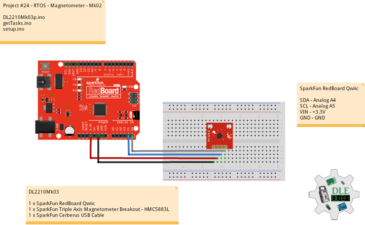
DL2210Mk03
1 x SparkFun RedBoard Qwiic
1 x SparkFun Triple Axis Magnetometer Breakout – HMC5883L
1 x SparkFun Cerberus USB Cable
SparkFun RedBoard Qwiic
SDA – Analog A4
SCL – Analog A5
VIN – +3.3V
GND – GND
DL2210Mk03p.ino
/* ***** Don Luc Electronics © ***** Software Version Information Project #24 - RTOS - Magnetometer - Mk02 24-02 DL2210Mk03p.ino 1 x SparkFun RedBoard Qwiic 1 x SparkFun Triple Axis Magnetometer Breakout - HMC5883L 1 x SparkFun Cerberus USB Cable */ // Include the Library Code // FreeRTOS #include <Arduino_FreeRTOS.h> // Two Wire Interface (TWI/I2C) #include <Wire.h> // Triple Axis Magnetometer #include <HMC5883L.h> // Define two tasks for Triple Axis Magnetometer void isTaskMagnetometer( void *pvParameters ); // Software Version Information String sver = "24-02"; void loop() { // Empty. Things are done in Tasks. }
getTasks.ino
// Tasks // Setup Task void isSetupTask(){ // Now set up one tasks to run independently // Magnetometer //xTaskCreatePinnedToCore( xTaskCreate( isTaskMagnetometer , "Magnetometer" , 128 // Stack size , NULL , 1 // Priority , NULL); // Now the task scheduler, which takes over control of scheduling individual tasks, // is automatically started. } // This is a Task Magnetometer Serial void isTaskMagnetometer(void *pvParameters) { (void) pvParameters; // Triple Axis Magnetometer HMC5883L compass; // Magnetometer Serial // Initialize HMC5883L Serial.println("Initialize HMC5883L"); while (!compass.begin()) { Serial.println("Could not find a valid HMC5883L sensor, check wiring!"); delay(500); } // Set measurement range // +/- 1.30 Ga: HMC5883L_RANGE_1_3GA (default) compass.setRange(HMC5883L_RANGE_1_3GA); // Set measurement mode // Continuous-Measurement: HMC5883L_CONTINOUS (default) compass.setMeasurementMode(HMC5883L_CONTINOUS); // Set data rate // 15.00Hz: HMC5883L_DATARATE_15HZ (default) compass.setDataRate(HMC5883L_DATARATE_15HZ); // Set number of samples averaged // 1 sample: HMC5883L_SAMPLES_1 (default) compass.setSamples(HMC5883L_SAMPLES_1); for (;;) { // Vector Norm Vector norm = compass.readNormalize(); // Vector X, Y, Z Serial.print("Xnorm = "); Serial.print(norm.XAxis); Serial.print(" Ynorm = "); Serial.print(norm.YAxis); Serial.print(" ZNorm = "); Serial.print(norm.ZAxis); Serial.println(); // One tick delay in between reads vTaskDelay(500); } }
setup.ino
// Setup void setup() { // Initialize serial communication // at 9600 bits per second: Serial.begin(9600); // Setup Task isSetupTask(); }
——
People can contact us: https://www.donluc.com/?page_id=1927
Technology Experience
- Single-Board Microcontrollers (PIC, Arduino, Raspberry Pi,Espressif, etc…)
- IoT
- Robotics
- Camera and Video Capture Receiver Stationary, Wheel/Tank and Underwater Vehicle
- Unmanned Vehicles Terrestrial and Marine
- Research & Development (R & D)
Instructor and E-Mentor
- IoT
- PIC Microcontrollers
- Arduino
- Raspberry Pi
- Espressif
- Robotics
Follow Us
J. Luc Paquin – Curriculum Vitae – 2022 English & Español
https://www.jlpconsultants.com/luc/
Web: https://www.donluc.com/
Web: https://www.jlpconsultants.com/
Facebook: https://www.facebook.com/neosteam.labs.9/
YouTube: https://www.youtube.com/channel/UC5eRjrGn1CqkkGfZy0jxEdA
Twitter: https://twitter.com/labs_steam
Pinterest: https://www.pinterest.com/NeoSteamLabs/
Instagram: https://www.instagram.com/neosteamlabs/
Don Luc
Project #24 – RTOS – FreeRTOS – Mk01
——
#DonLucElectronics #DonLuc #ESP32 #RTOS #FreeRTOS #Arduino #Project #Fritzing #Programming #Electronics #Microcontrollers #Consultant
——
——
——
——
Real-Time Operating System
A real-time operating system (RTOS) is an operating system for real-time applications that processes data and events that have critically defined time constraints. A RTOS is distinct from a time-sharing operating system, such as Unix, which manages the sharing of system resources with a scheduler, data buffers, or fixed task prioritization in a multitasking or multiprogramming environment. Processing time requirements need to be fully understood and bound rather than just kept as a minimum. All processing must occur within the defined constraints. Real-time operating systems are event-driven and preemptive, meaning the OS is capable of monitoring the relevant priority of competing tasks, and make changes to the task priority. Event-driven systems switch between tasks based on their priorities, while time-sharing systems switch the task based on clock interrupts.
FreeRTOS
FreeRTOS is a real-time operating system kernel for embedded devices that has been ported to 35 microcontroller platforms. It is distributed under the MIT License. FreeRTOS is designed to be small and simple. It is mostly written in the C programming language to make it easy to port and maintain. It also comprises a few assembly language functions where needed, mostly in architecture-specific scheduler routines.
FreeRTOS is ideally suited to deeply embedded real-time applications that use microcontrollers or small microprocessors. This type of application normally includes a mix of both hard and soft real-time requirements. Soft real-time requirements are those that state a time deadline, but breaching the deadline would not render the system useless. For example, responding to keystrokes too slowly might make a system seem annoyingly unresponsive without actually making it unusable.
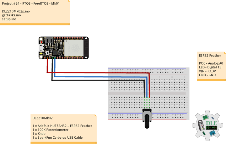
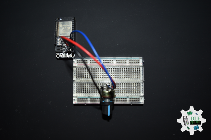
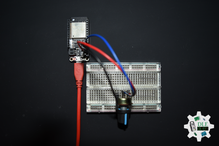
DL2210Mk02
1 x Adafruit HUZZAH32 – ESP32 Feather
1 x 100K Potentiometer
1 x Knob
1 x SparkFun Cerberus USB Cable
ESP32 Feather
PO0 – Analog A0
LED – Digital 13
VIN – +3.3V
GND – GND
DL2210Mk02p.ino
/* ***** Don Luc Electronics © ***** Software Version Information Project #24 - RTOS - FreeRTOS - Mk01 24-01 DL2210Mk02p.ino 1 x Adafruit HUZZAH32 – ESP32 Feather 1 x 100K Potentiometer 1 x Knob 1 x SparkFun Cerberus USB Cable */ // Include the Library Code // FreeRTOS ESP32 #if CONFIG_FREERTOS_UNICORE #define ARDUINO_RUNNING_CORE 0 #else #define ARDUINO_RUNNING_CORE 1 #endif // Led Built In #ifndef LED_BUILTIN #define LED_BUILTIN 13 #endif // Define two tasks for Blink & AnalogRead void isTaskBlink( void *pvParameters ); void isTaskAnalogReadA0( void *pvParameters ); // Software Version Information String sver = "24-01"; void loop() { // Empty // Things are done in Tasks }
getTasks.ino
// Tasks // This is a Task Blink void isTaskBlink(void *pvParameters) { (void) pvParameters; // Blink // Turns on an LED on for 2 second, then off for 2 second, repeatedly // Initialize digital LED_BUILTIN on pin 13 as an output. pinMode(LED_BUILTIN, OUTPUT); // A Task shall never return or exit for (;;) { // Turn the LED on (HIGH is the voltage level) digitalWrite(LED_BUILTIN, HIGH); // One tick delay in between reads vTaskDelay(2000); // Turn the LED off by making the voltage LOW digitalWrite(LED_BUILTIN, LOW); // One tick delay in between reads vTaskDelay(2000); } } // This is a Task Analog Read Serial void isTaskAnalogReadA0(void *pvParameters) { (void) pvParameters; // Analog Read Serial // Reads an analog input on pin A0, prints the result to the serial monitor for (;;) { // Read the input on analog pin A0 int sensorValueA0 = analogRead(A0); // Print out the value you read Serial.print( "Pot A0: " ); Serial.println(sensorValueA0); // One tick delay (15ms) in between reads for stability vTaskDelay(100); } }
setup.ino
// Setup void setup() { // Initialize serial communication // at 115200 bits per second Serial.begin(115200); // Now set up two tasks to run independently // TaskBlink xTaskCreatePinnedToCore( isTaskBlink , "TaskBlink" // A name just for humans , 1024 // This stack size can be checked & adjusted by reading. , NULL , 2 // Priority, with 2 being the highest, and 0 being the lowest. , NULL , ARDUINO_RUNNING_CORE); // AnalogReadA0 xTaskCreatePinnedToCore( isTaskAnalogReadA0 , "AnalogReadA0" , 1024 // Stack size , NULL , 1 // Priority , NULL , ARDUINO_RUNNING_CORE); // Now the task scheduler, which takes over control of scheduling individual tasks, // is automatically started. }
——
People can contact us: https://www.donluc.com/?page_id=1927
Technology Experience
- Single-Board Microcontrollers (PIC, Arduino, Raspberry Pi,Espressif, etc…)
- IoT
- Robotics
- Camera and Video Capture Receiver Stationary, Wheel/Tank and Underwater Vehicle
- Unmanned Vehicles Terrestrial and Marine
- Research & Development (R & D)
Instructor and E-Mentor
- IoT
- PIC Microcontrollers
- Arduino
- Raspberry Pi
- Espressif
- Robotics
Follow Us
J. Luc Paquin – Curriculum Vitae – 2022 English & Español
https://www.jlpconsultants.com/luc/
Web: https://www.donluc.com/
Web: https://www.jlpconsultants.com/
Facebook: https://www.facebook.com/neosteam.labs.9/
YouTube: https://www.youtube.com/channel/UC5eRjrGn1CqkkGfZy0jxEdA
Twitter: https://twitter.com/labs_steam
Pinterest: https://www.pinterest.com/NeoSteamLabs/
Instagram: https://www.instagram.com/neosteamlabs/
Don Luc