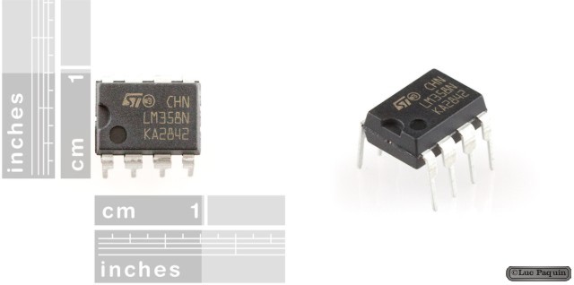
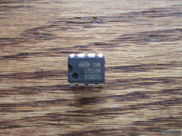
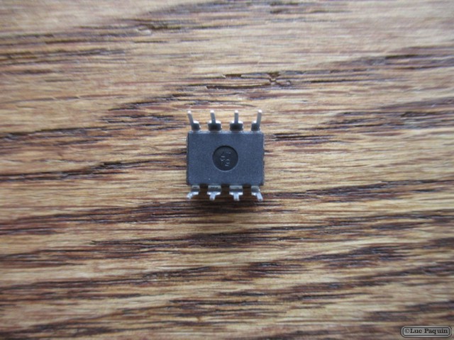
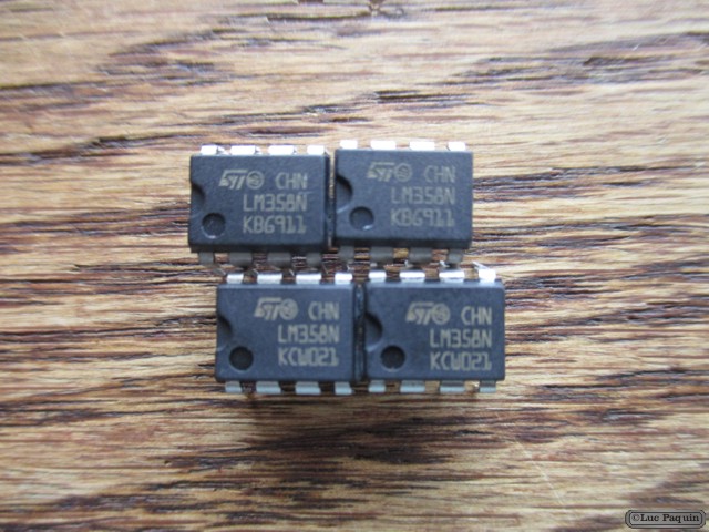
SparkFun – Op-Amp (Thru-Hole) – LM358
SparkFun: COM-09456
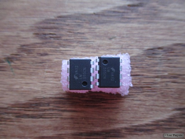
Description: The LM358 is a great, easy-to-use dual-channel opamp. Opamps have so many applications we figured we should probably carry at least one in a DIP package. LM358 applications include transducer amplifiers, DC gain blocks and all the conventional opamp circuits.
If you’re looking for a good, standard opamp the LM358 should fill most of your needs. It can handle a supply of 3-32VDC and source up to 20mA per channel. This opamp is great if you need to operate two individual opamps from a single power supply. Comes in an 8-pin DIP package.
Features:
- Two internally compensated op-amps
- Internally frequency compensated for unity gain
- Large DC voltage gain: 100 dB
- Wide bandwidth (unity gain): 1 MHz (temperature compensated)
- Wide power supply range:
- Single supply: 3V to 32V
- or dual supplies: +/-1.5V to +/-16V
Don Luc
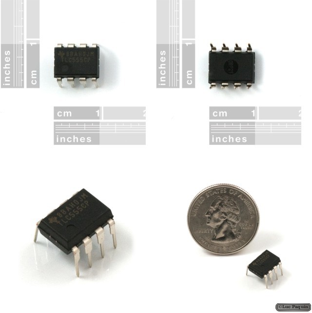
SparkFun – 555 Timer
SparkFun: COM-09273
Description: This is a common 555 timer/oscillator from TI. A classic for all of those first year circuits projects where you need to blink an LED, generate tone, and thousands of other great beginning projects. Google around for a huge list of resources and example projects.
Features:
- 4.5V to 16V supply
- 8-pin DIP package
- Timing from microseconds to hours
- Astable or monostable operation
- Adjustable duty cycle
- TTL compatible output
- Sink or source up to 200mA
Don Luc
SparkFun – OpenLog
SparkFun: DEV-09530
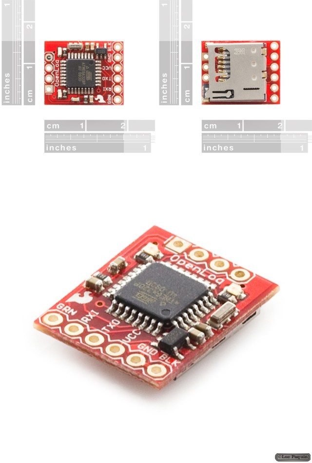
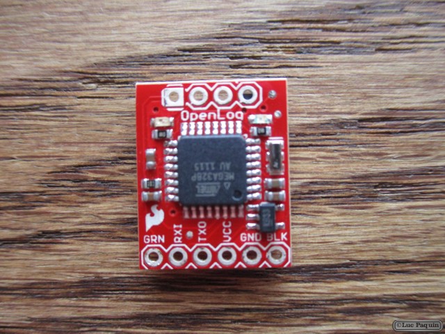
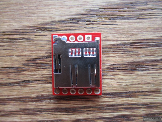
Description: The SparkFun OpenLog is an open source data logger. Simple to use, simple to change. We wanted to create a serial logger that just worked. Power up this device and it will start logging any received serial data at 9600bps. Sending Ctrl+z three times will drop out of logging and in to command mode. ‘new’ will create a new file. ‘md’ makes a directory. ‘?’ brings up the list of commands. OpenLog doesn’t do a lot, but it does log serial streams extremely well.
Example:
 >new testfile.txt
 >append testfile.txt
 <(send large amounts of text followed by three ctrl+z characters)
That’s really it! OpenLog firmware is open source and is based on Bill Greiman’s sdfatlib. OpenLog currently supports FAT16 and FAT32 microSD cards (we’ve tested up to 64GB!).
All the design files (schematic, PCB layout, firmware) are open source released under the CC-SA v3 license and are available through GitHub.
Note: New firmware is available which allows the OpenLog to be used in Arduino 1.0 and also allows for higher baud rates. Check the links below for more information.
Features:
- Log to low-cost microSD FAT16/32 cards up to 16GB
- Simple command interface
- Edit config.txt file from a computer to change baud rate and other system settings
- Three modes:
- NewLog creates a new log every power up and immediately starts logging
- SeqLog appends a file called “SeqLog.txt” at every power up and immediately starts logging
- Command mode starts OpenLog at a command prompt at power up
- Configurable baud rates (2400 to 115200bps)
- Configure unit through config file or the menu system
- Power, ground, and RX-I are the minimum connections
- Reprogrammable ATmega328 using the Arduino IDE
- Two LEDs indicate writing status
- Input voltage from 3.3V to 12V
- 2mA idle, 6mA at maximum recording rate
Dimensions: 0.16 x 0.6 x 0.75″ (4 x 15 x 19mm)
Don Luc
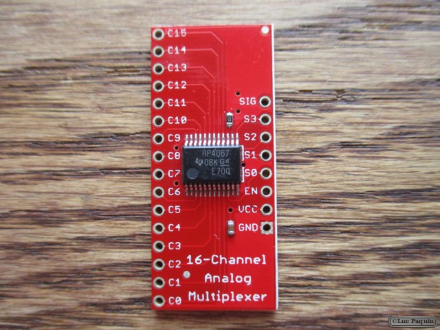
SparkFun – Analog/Digital MUX Breakout – CD74HC4067
SparkFun: BOB-09056
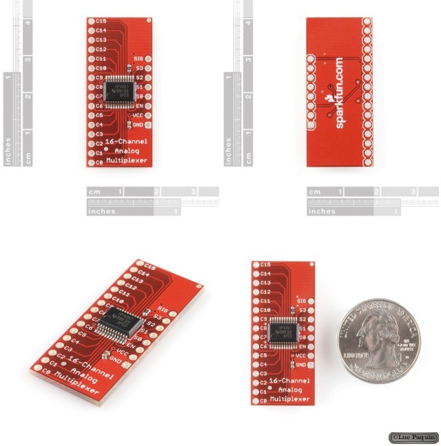
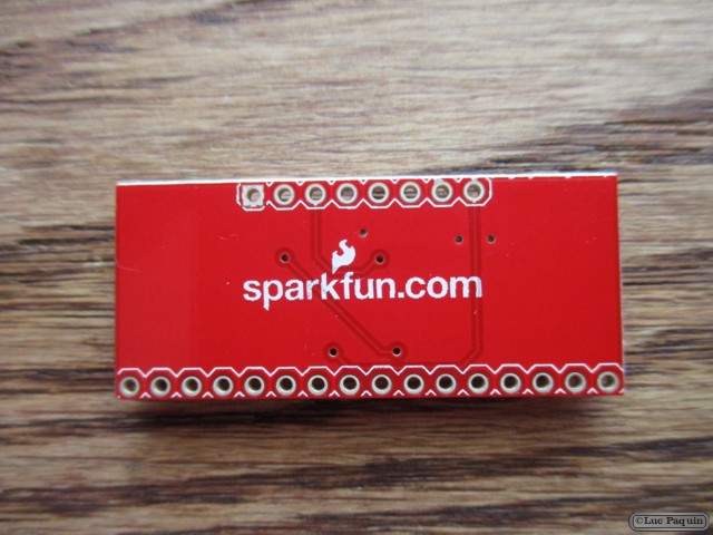
Description: This is a breakout board for the very handy 16-Channel Analog/Digital Multiplexer/Demultiplexer CD74HC4067. This chip is like a rotary switch – it internally routes the common pin (COM in the schematic, SIG on the board) to one of 16 channel pins (CHANxx). It works with both digital and analog signals (the voltage can’t be higher than VCC), and the connections function in either direction. To control it, connect 4 digital outputs to the chip’s address select pins (S0-S3), and send it the binary address of the channel you want (see the datasheet for details). This allows you to connect up to 16 sensors to your system using only 5 pins!
Since the mux/demux also works with digital signals, you can use it to pipe TTL-level serial data to or from multiple devices. For example, you could use it to connect the TX pins of 16 devices to one RX pin on your microcontroller. You can then select any one of those 16 devices to listen to. If you want two-way communications, you can add a second board to route your microcontroller’s TX line to 16 device’s RX lines. By using multiple boards, you can create similar arrangements for I2C, SPI, etc.
The internal switches are bidirectional, support voltages between ground and VCC, have low “on” resistance and low “off” leakage, and to prevent crosstalk, perform “break-before-make” switching. The board also breaks out the chip’s “enable” pin, which when driven high, will completely disconnect the common pin (all switches “off”).
Features:
- 2V to 6V operation
- “On” resistance: 70 Ohms @ 4.5V
- 6ns break-before-make @ 4.5V
- Wide operating temperature range: -55C to 125C
Don Luc
SparkFun – IC Hook with Pigtail
SparkFun: CAB-09741
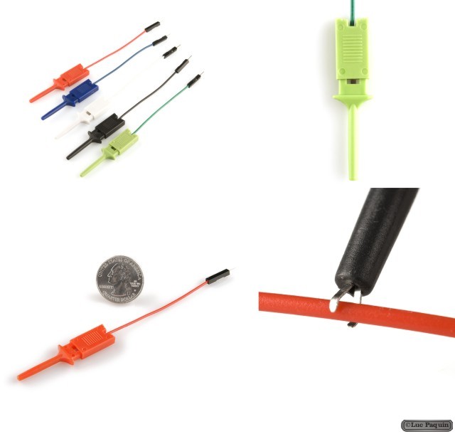
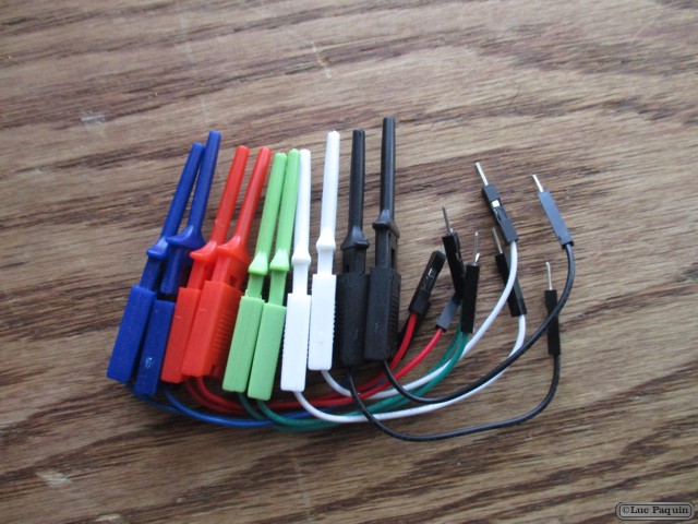
Description: These are good quality IC test hooks with a male connection wire. Instead of a single hook, these have two hooks that are capable of grabbing very small points (like SOIC IC legs). Comes in a bag of five IC hooks of different colors (black, red, white, blue, and green). We use them with the Bus Pirate logic analyzer harnesses but are very cool on their own.
Wire length is 2.5″ long. Male pin easily inserts into breadboard or other standard 0.1″ connector.
Don Luc
SparkFun – LinkM – USB to I2C
SparkFun: COM-09903
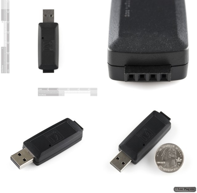
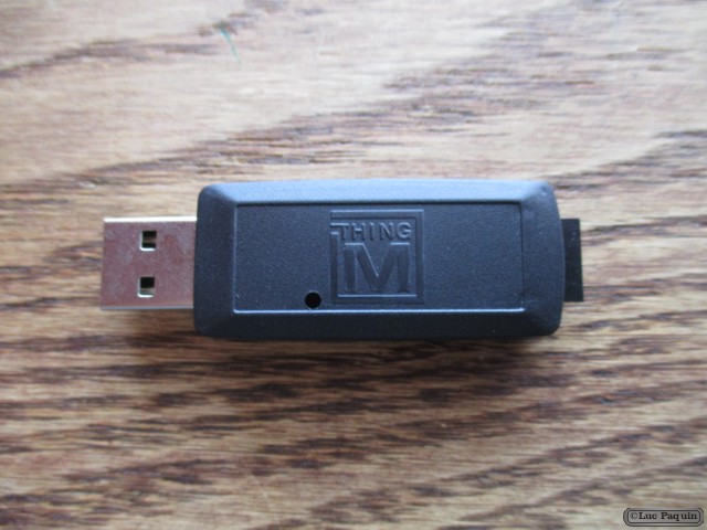
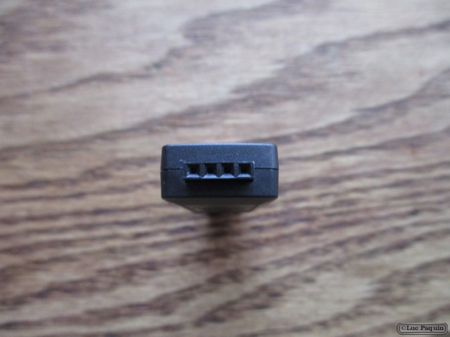
Description: LinkM is a USB adapter that addresses two of the most frequently-requested BlinkM features. It enables you to program BlinkMs without setting up a separate I/O board, such as an Arduino. It also lets you program or control multiple BlinkMs simultaneously. Plug it in, plug in a BlinkM, fire up the BlinkM Multitrack Sequencer, and start programming BlinkMs. It requires no drivers (when used with most operating systems), additional software or hardware. BlinkM’s sold separately.
Features:
- Driverless. Identifies itself as a USB Human Interface (HID) class device, which nearly every operating system supports without requiring additional drivers.
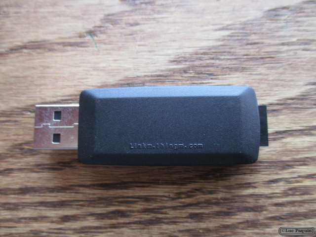
- Has no exposed components. Its hard plastic case makes it appropriate for long-term installation.
- Synchronizes groups of BlinkMs with a metronome signal so that their patterns do not drift in time (this even works when the LinkM is only connected to a power supply, such as an iPod USB charger).
- Works as a generic USB->I2C device, making it compatible with hundreds of standard I2C devices.
- Contains an I2C buffer chip for driving longer I2C bus cables.
- Open Source firmware, available from Google Code
- Open Source libraries for C, Java and Processing that work on Mac OS X, Windows XP/7 and Ubuntu Linux, also available from Google Code.
- Acts as an I2C master with built-in BlinkM metronome for synchronizing groups of BlinkMs so that their patterns do not drift with time
- Additional I/O pins on the board. AVR hackers can crack open the case to get access to digital I/O pins and use LinkM as a standalone microcontroller platform.
Don Luc
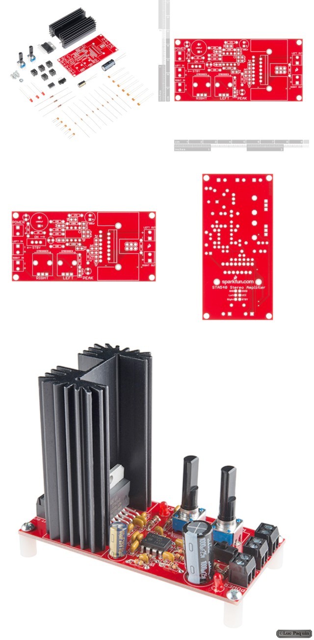
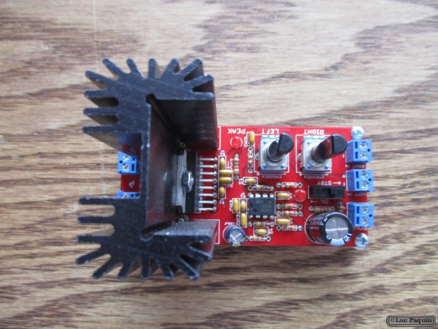
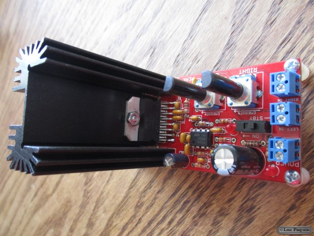
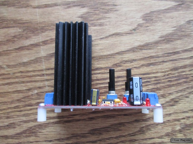
SparkFun – Audio Amplifier Kit – STA540
SparkFun: KIT-09612
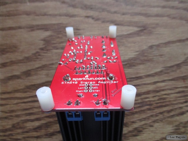
Description: This is a stereo amplifier kit designed to make use of the STA540 power amplifier IC. Once this kit is completed you have a fully functional, two-channel audio amplifier, complete with a standby switch, volume control and indicator LEDs. The kit also includes a 6400BG heatsink for the STA540 to dissipate any damaging heat.
In this kit, the STA540 is configured as a dual bridge amplifier capable of delivering up to 2x 38W (4O at 18V). Power supplied to the kit directly powers the STA540 and should be within 8 to 22V.
This kit comes as a bag of parts, you’ll need to solder everything to the PCB. All components are through-hole, so it shouldn’t be too difficult; but this kit is a bit more complex than our other through-hole kits.
Kit Includes:
- 1 x STA540 Audio Amplifier Kit PCB
- 1 x STA540 Dual/Quad Power Amplifier
- 1 x 6400BG Heatsink
- 1 x LM358 Op Amp
- 3 x LED – Basic Red
- 1 x SPDT Mini Power Switch
- Resistors:
- 5 x 10K Ohm
- 3 x 1.0K Ohm
- 2 x 47k Ohm
- 2 x 100k Ohm
- 2 x 10k Giant Trimpot
- Capacitors:
- 1 x 0.1uF-50V-20%
- 1 x 100uF – 25V
- 4 x 0.47uF-25V
- 2 x 10pF – 200V – 5%
- 3 x 1uF – 50V – -20,+80%
- 1 x 1000uF/25V
- 5 x 2-Pin Screw Terminal – 3.5mm
- 4 x Nylon Round Female Standoff
- 5 x Phillips Screw with 4-40 Thread
- 1 x #4-40 Hex Nut
Don Luc
SparkFun – Arduino Mega 2560 R2
SparkFun: DEV-09949
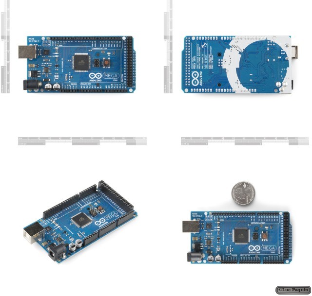
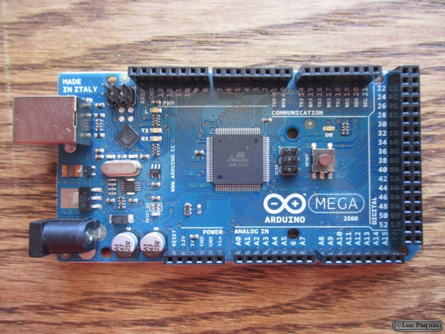
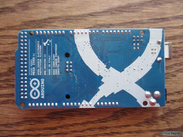
Description: Arduino is an open-source physical computing platform based on a simple i/o board and a development environment that implements the Processing/Wiring language. Arduino can be used to develop stand-alone interactive objects or can be connected to software on your computer (e.g. Flash, Processing, MaxMSP). The open-source IDE can be downloaded for free (currently for Mac OS X, Windows, and Linux).
The Arduino Mega is a microcontroller board based on the ATmega2560. It has 54 digital input/output pins (of which 14 can be used as PWM outputs), 16 analog inputs, 4 UARTs (hardware serial ports), a 16 MHz crystal oscillator, a USB connection, a power jack, an ICSP header, and a reset button. It contains everything needed to support the microcontroller; simply connect it to a computer with a USB cable or power it with a AC-to-DC adapter or battery to get started. The Mega is compatible with most shields designed for the Arduino Duemilanove or Diecimila.
This is the new Arduino Mega 2560. In addition to all the features of the previous board, the Mega 2560 now uses an ATmega8U2 instead of the FTDI chip. This allows for faster transfer rates, no drivers needed for Linux or Mac (inf file for Windows is needed), and the ability to have the board show up as a keyboard, mouse, joystick, etc. It also has twice as much flash memory.
Features:
- ATmega2560 microcontroller
- Input voltage – 7-12V
- 54 Digital I/O Pins (14 PWM outputs)
- 16 Analog Inputs
- 256k Flash Memory
- 16Mhz Clock Speed
Don Luc
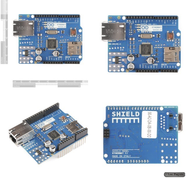
SparkFun – Arduino Ethernet Shield
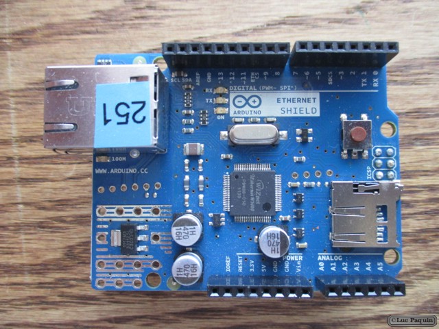
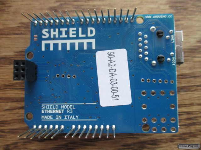
SparkFun: DEV-09026
Description: The Arduino Ethernet Shield allows an Arduino board to connect to the internet. It is based on the Wiznet W5100 ethernet chip providing a network (IP) stack capable of both TCP and UDP. The Arduino Ethernet Shield supports up to four simultaneous socket connections. Use the Ethernet library to write sketches which connect to the internet via a standard RJ45 Ethernet jack using the shield.
The latest revision of the shield adds a micro-SD card slot, which can be used to store files for serving over the network. It is compatible with the Arduino Uno and Mega (using the Ethernet library). You can access the on-board SD card slot using the SD library which is included in the current Arduino build.
The latest revision of the shield also includes a reset controller, to ensure that the W5100 Ethernet module is properly reset on power-up. Previous revisions of the shield were not compatible with the Mega and need to be manually reset after power-up. The reset button on the shield resets both the W5100 and the Arduino board.
Arduino communicates with both the W5100 and SD card using the SPI bus (through the ICSP header). This is on digital pins 11, 12, and 13 on the Duemilanove and pins 50, 51, and 52 on the Mega. On both boards, pin 10 is used to select the W5100 and pin 4 for the SD card. These pins cannot be used for general i/o. On the Mega, the hardware SS pin, 53, is not used to select either the W5100 or the SD card, but it must be kept as an output or the SPI interface won’t work.
Note that because the W5100 and SD card share the SPI bus, only one can be active at a time. If you are using both peripherals in your program, this should be taken care of by the corresponding libraries. If you’re not using one of the peripherals in your program, however, you’ll need to explicitly deselect it. To do this with the SD card, set pin 4 as an output and write a high to it. For the W5100, set digital pin 10 as a high output.
Don Luc
SparkFun – MIDI Shield
SparkFun: DEV-09595
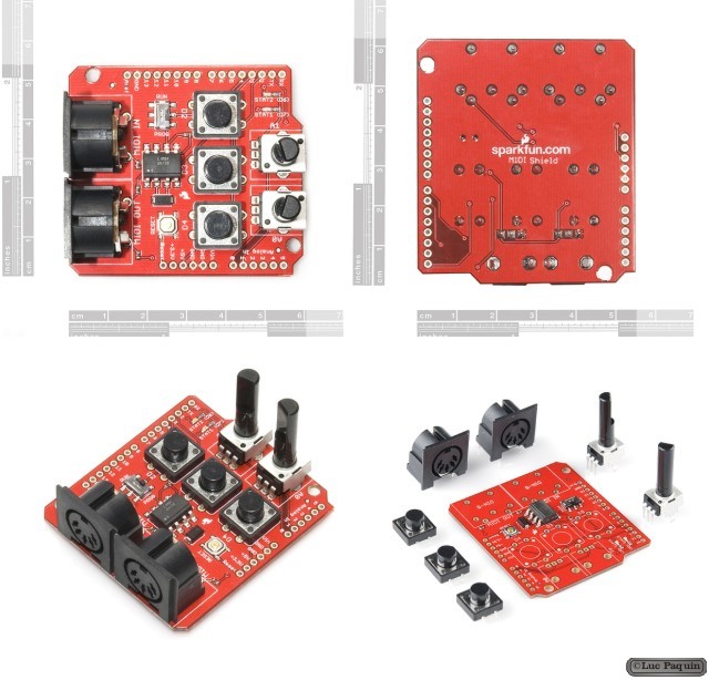
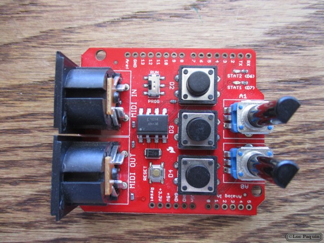
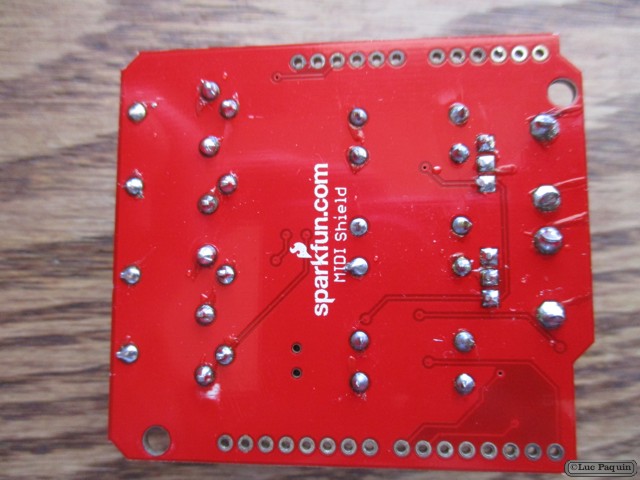
Description: The SparkFun MIDI Shield board gives your Arduino access to the antiquated, but still widely used and well supported MIDI communication protocol, so you can control synthesizers, sequencers, and other musical devices. The MIDI protocol shares many similarities with standard asynchronous serial interfaces, so you can use the UART pins of your Arduino to send and receive MIDI’s event messages.
The MIDI Shield provides an opto-isolated MIDI-IN port as well as a MIDI-OUT port. The MIDI Shield can be mounted directly on top of an Arduino, connecting the MIDI-IN to the Arduino’s hardware RX pin and the MIDI-OUT to TX. Potentiometers are connected to analog pins 1 and 2, and can be used to control volume, pitch, tone or anything else you’d like. Also connected on the shield are three momentary push buttons (connected to D2-4), a reset button, and green and red stat LEDs. The RUN/PROG switch allows you to program the Arduino over serial without having to remove the shield.
Note: The MIDI Shield does not come with the through-hole MIDI connectors or trimpots soldered on. All of these components (2 MIDI connectors and 2 trimpots) are included with the product, however
Note: When using this shield with the Arduino Pro you will have to bypass the TX/RX resistors on the Pro to get enough current to the shield.
Don Luc
