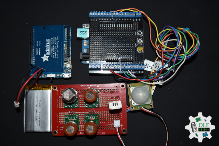
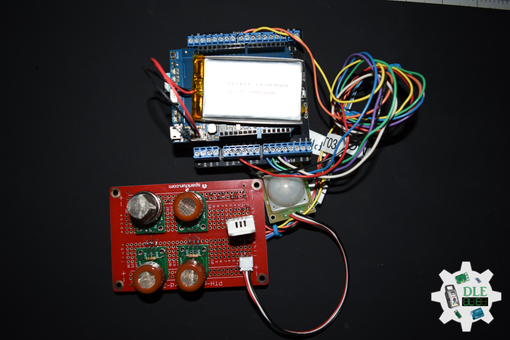
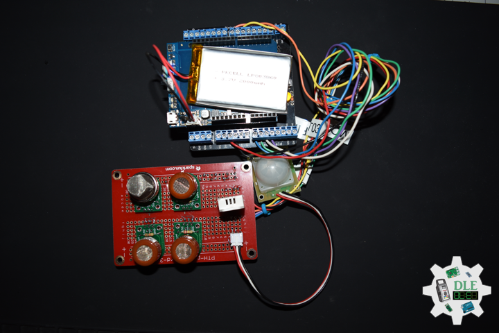
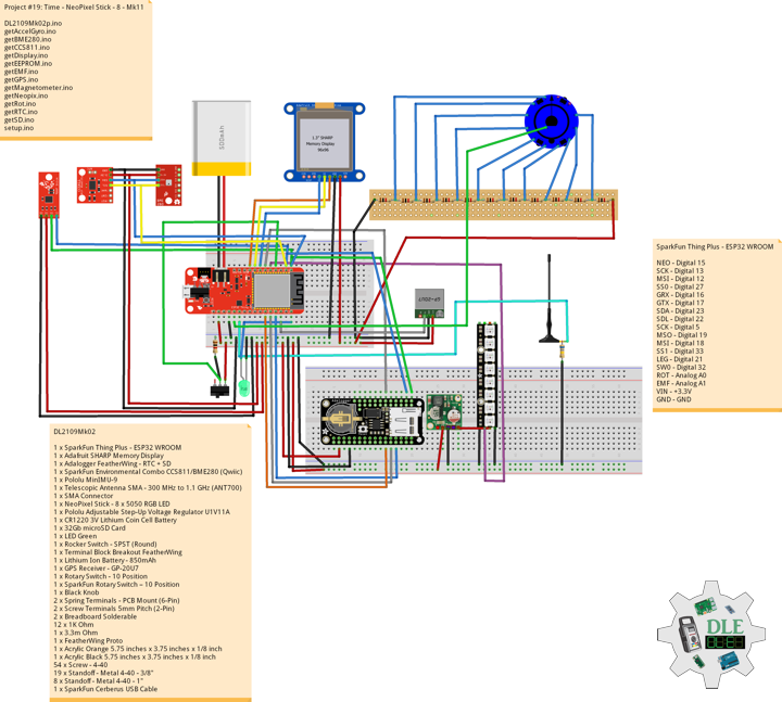
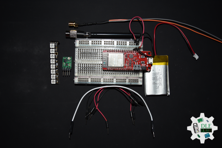
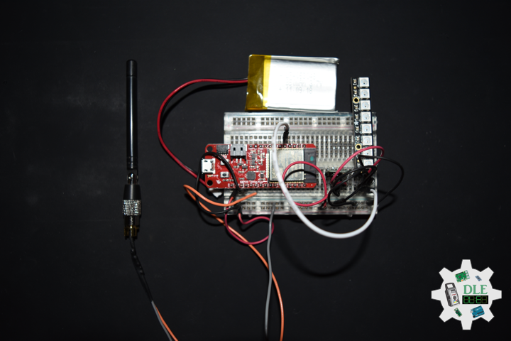
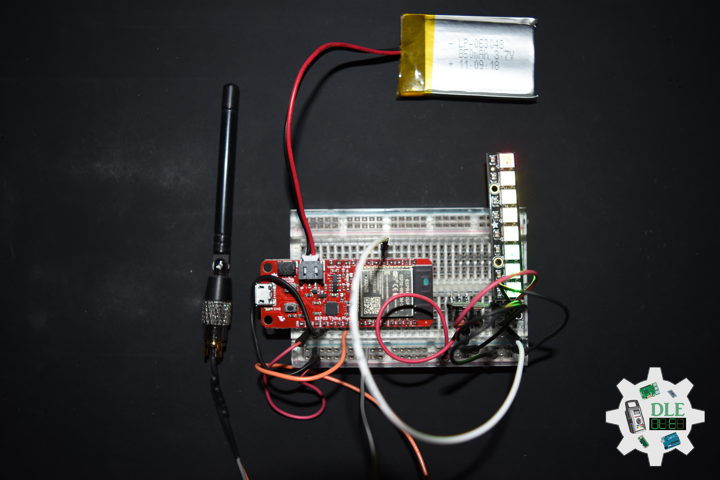
Battery
Project #19: Time – GPS Receiver – GP-20U7 – Mk03
——
#DonLucElectronics #DonLuc #Time #DS3231PrecisionRTC #SHARPMemoryDisplay #GPSReceiver #Arduino #ESP32 #SparkFunThingPlusESP32WROOM #Project #Programming #Electronics #Microcontrollers #Consultant #VideoBlog
——
——
——
——
——
——
GPS Receiver – GP-20U7
The GP-20U7 is a compact GPS receiver with a built-in high performances all-in-one GPS chipset. The GP-20U7 accurately provides position, velocity, and time readings as well possessing high sensitivity and tracking capabilities. Thanks to the low power consumption this receiver requires, the GP-20U7 is ideal for portable applications such as tablet PCs, smart phones, and other devices requiring positioning capability.
This 56-channel GPS module, that supports a standard NMEA-0183 and uBlox 7 protocol, has low power consumption of 40mA@3.3V (max), an antenna on board, and -162dBm tracking sensitivity. With 56 channels in search mode and 22 channels “all-in-view” tracking, the GP-20U7 is quite the work horse for its size.
This one is unused and doesnt have a conection TX pin.
NMEA V3.01 Protocol
- Its output signal level is TTL: 9600bps (default), 8 bit data, 1 stop bit and no parity
- It supports the following NMEA-0183
- Messages: GGA, GLL, GSA, GSV, RMC and VTG
NMEA-0183 Output Messages
- NMEA: Record Description
- GGA: Global positoning system fixed data
- GLL: Geogrphic position – latitude / longitude
- GSA: GNSS DOP and active satellites
- GSV: GNSS satellites in view
- RMC: Recommended minimum specific GNSS data
- VTG: Course over ground and ground speed
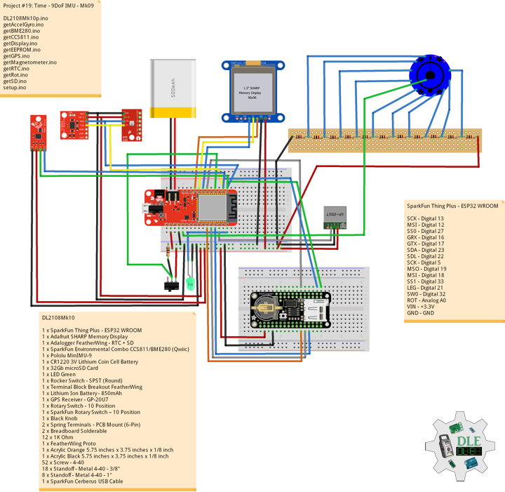
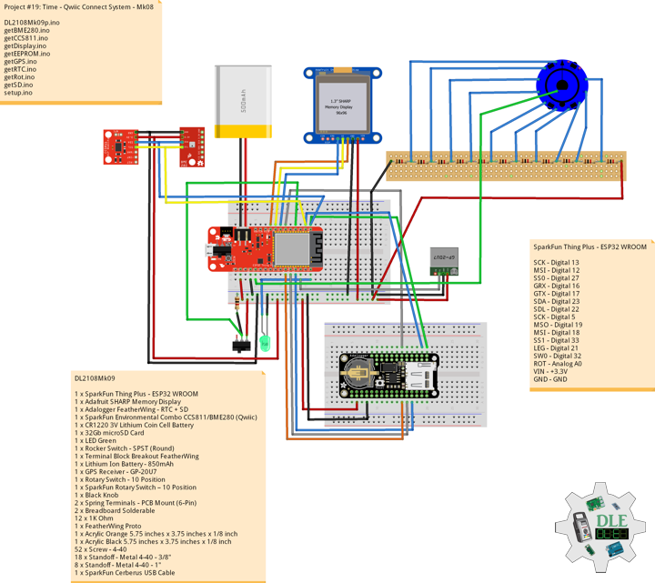
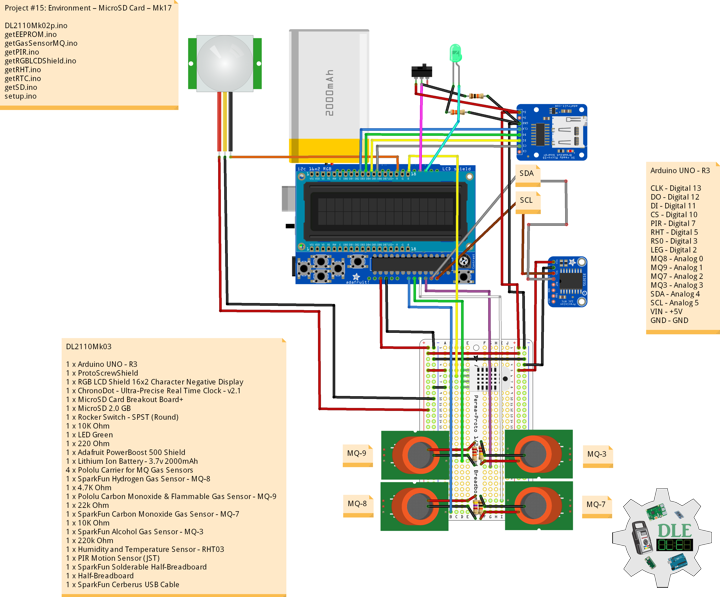
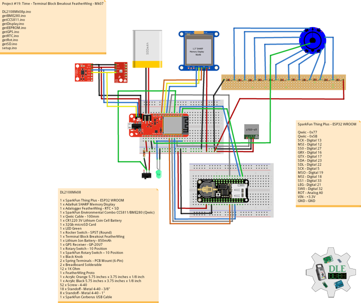
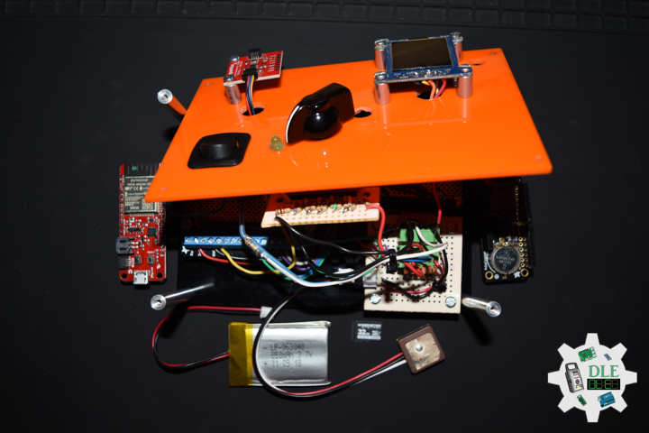
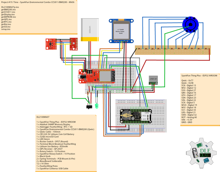
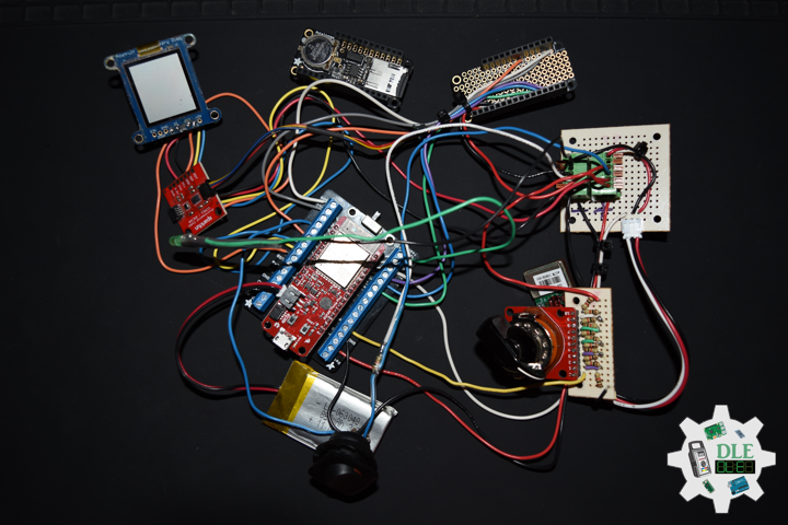
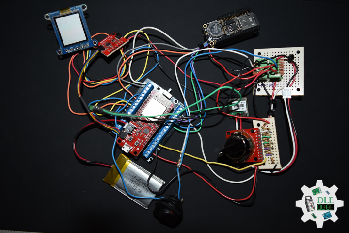
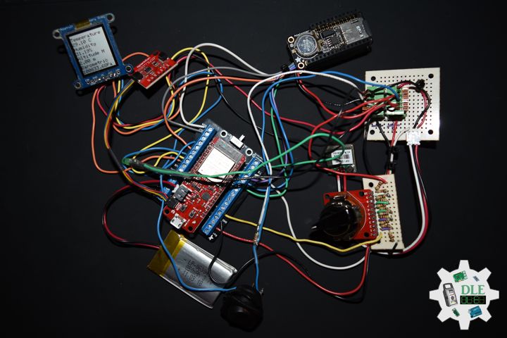
DL2108Mk03
1 x SparkFun Thing Plus – ESP32 WROOM
1 x Adafruit SHARP Memory Display
1 x DS3231 Precision RTC FeatherWing
1 x CR1220 3V Lithium Coin Cell Battery
1 x Terminal Block Breakout FeatherWing
1 x Lithium Ion Battery – 850mAh
1 x GPS Receiver – GP-20U7
1 x Half-Size Breadboard
1 x SparkFun Cerberus USB Cable
SparkFun Thing Plus – ESP32 WROOM
SCK – Digital 13
MSI – Digital 12
SS0 – Digital 27
GRX – Digital 16
GTX – Digital 17
SDA – Digital 23
SDL – Digital 22
VIN – +3.3V
GND – GND
DL2108Mk03p.ino
/* ***** Don Luc Electronics © ***** Software Version Information Project #19: Time -GPS Receiver - GP-20U7 - Mk03 08-03 DL2108Mk03p.ino 1 x SparkFun Thing Plus - ESP32 WROOM 1 x Adafruit SHARP Memory Display 1 x DS3231 Precision RTC FeatherWing 1 x CR1220 3V Lithium Coin Cell Battery 1 x Terminal Block Breakout FeatherWing 1 x Lithium Ion Battery - 850mAh 1 x GPS Receiver - GP-20U7 1 x Half-Size Breadboard 1 x SparkFun Cerberus USB Cable */ // Include the Library Code // Wire // #include <Wire.h> // SHARP Memory Display #include <Adafruit_SharpMem.h> #include <Adafruit_GFX.h> // Date and time DS3231 RTC #include <RTClib.h> // GPS Receiver #include <TinyGPS++.h> // ESP32 Hardware Serial #include <HardwareSerial.h> // SHARP Memory Display #define SHARP_SCK 13 #define SHARP_MOSI 12 #define SHARP_SS 27 // Set the size of the display here, e.g. 144x168! Adafruit_SharpMem display(SHARP_SCK, SHARP_MOSI, SHARP_SS, 144, 168); // The currently-available SHARP Memory Display (144x168 pixels) // requires > 4K of microcontroller RAM; it WILL NOT WORK on Arduino Uno // or other <4K "classic" devices. #define BLACK 0 #define WHITE 1 // Date and time functions using a DS3231 RTC RTC_DS3231 RTC; String sDate; String sTime; // ESP32 HardwareSerial HardwareSerial tGPS(2); // GPS Receiver #define gpsRXPIN 16 // This one is unused and doesnt have a conection #define gpsTXPIN 17 // The TinyGPS++ object TinyGPSPlus gps; float TargetLat; float TargetLon; int GPSStatus = 0; String GPSSt = ""; // Software Version Information // Version String sver = "19-03"; void loop() { // Dates and Time timeRTC(); // isGPS isGPS(); // Display Date, Time, GPS isDisplayDate(); delay( 1000 ); }
getDisplay.ino
// SHARP Memory Display // SHARP Memory Display - UID void isDisplayUID() { // Text Display // Clear Display display.clearDisplay(); display.setRotation(4); display.setTextSize(3); display.setTextColor(BLACK); // Don Luc Electronics display.setCursor(0,10); display.println( "Don Luc" ); display.setTextSize(2); display.setCursor(0,40); display.println( "Electronics" ); // Version display.setTextSize(3); display.setCursor(0,70); display.println( "Version" ); display.setTextSize(2); display.setCursor(0,100); display.println( sver ); // Refresh display.refresh(); delay( 100 ); } // Display Date void isDisplayDate() { // Text Display Date // Clear Display display.clearDisplay(); display.setRotation(4); display.setTextSize(2); display.setTextColor(BLACK); // Date display.setCursor(0,5); display.println( sDate ); // Time display.setCursor(0,30); display.println( sTime ); // GPS Status display.setCursor(0,55); display.print( "GPS: " ); display.println( GPSSt ); // Target Latitude display.setCursor(0,75); display.println( "Latitude" ); display.setCursor(0,100); display.println( TargetLat ); // Target Longitude display.setCursor(0,120); display.println( "Longitude" ); display.setCursor(0,145); display.println( TargetLon ); // Refresh display.refresh(); delay( 100 ); }
getGPS.ino
// GPS Receiver // Setup GPS void setupGPS() { // Setup GPS tGPS.begin( 9600 , SERIAL_8N1 , gpsRXPIN , gpsTXPIN ); } // isGPS void isGPS(){ // Receives NEMA data from GPS receiver // This sketch displays information every time a new sentence is correctly encoded while ( tGPS.available() > 0) if (gps.encode( tGPS.read() )) { // GPS Vector Pointer Target displayInfo(); } if (millis() > 5000 && gps.charsProcessed() < 10) { while(true); } } // GPS Vector Pointer Target void displayInfo(){ // Location if (gps.location.isValid()) { // Latitude TargetLat = gps.location.lat(); // Longitude TargetLon = gps.location.lng(); // GPS Status 2 GPSStatus = 2; GPSSt = "Yes"; } else { // GPS Status 0 GPSStatus = 0; GPSSt = "No"; } }
getRTCDS3231.ino
// DS3231 Precision RTC // Setup RTC void setupRTC() { // DS3231 Precision RTC RTC.begin(); if (! RTC.begin()) { while (1); } // Date Time DateTime now = RTC.now(); if (RTC.lostPower()) { // Following line sets the RTC to the date & time this sketch was compiled RTC.adjust(DateTime(F(__DATE__), F(__TIME__))); // This line sets the RTC with an explicit date & time, for example to set // August 2, 2021 at 13:53:0 you would call: // RTC.adjust(DateTime(2021, 8, 2, 14, 11, 0)); } } // timeRTC void timeRTC() { // DS3231 Precision RTC sDate = ""; sTime = ""; // Date Time DateTime now = RTC.now(); // sData sDate += String(now.year(), DEC); sDate += "/"; sDate += String(now.month(), DEC); sDate += "/"; sDate += String(now.day(), DEC); // sTime sTime += String(now.hour(), DEC); sTime += ":"; sTime += String(now.minute(), DEC); sTime += ":"; sTime += String(now.second(), DEC); }
setup.ino
// Setup void setup() { // GPS Receiver // Setup GPS setupGPS(); // Set up I2C bus // Wire.begin(); // SHARP Display Start & Clear the Display display.begin(); // Clear Display display.clearDisplay(); // Display UID isDisplayUID(); // Setup RTC setupRTC(); delay( 5000 ); }
——
People can contact us: https://www.donluc.com/?page_id=1927
Technology Experience
- Single-Board Microcontrollers (PIC, Arduino, Raspberry Pi,Espressif, etc…)
- IoT
- Robotics
- Research & Development (R & D)
- Desktop Applications (Windows, OSX, Linux, Multi-OS, Multi-Tier, etc…)
- Mobile Applications (Android, iOS, Blackberry, Windows Mobile, Windows CE, etc…)
- Web Applications (LAMP, Scripting, Java, ASP, ASP.NET, RoR, Wakanda, etc…)
- Social Media Programming & Integration (Facebook, Twitter, YouTube, Pinterest, etc…)
- Content Management Systems (WordPress, Drupal, Joomla, Moodle, etc…)
- Bulletin Boards (phpBB, SMF, Vanilla, jobberBase, etc…)
- eCommerce (WooCommerce, OSCommerce, ZenCart, PayPal Shopping Cart, etc…)
Instructor
- PIC Microcontrollers
- Arduino
- Raspberry Pi
- Espressif
- Robotics
- DOS, Windows, OSX, Linux, iOS, Android, Multi-OS
- Linux-Apache-PHP-MySQL
Follow Us
J. Luc Paquin – Curriculum Vitae – 2021 English & Español
https://www.jlpconsultants.com/CV/LucPaquinCVEngMk2021c.pdf
https://www.jlpconsultants.com/CV/LucPaquinCVEspMk2021c.pdf
Web: https://www.donluc.com/
Web: https://www.jlpconsultants.com/
Web: https://www.donluc.com/DLE/
Web: https://www.donluc.com/DLHackster/
Web: https://www.hackster.io/neosteam-labs
Web: https://zoom.us/
Patreon: https://www.patreon.com/DonLucElectronics
Facebook: https://www.facebook.com/neosteam.labs.9/
YouTube: https://www.youtube.com/channel/UC5eRjrGn1CqkkGfZy0jxEdA
Twitter: https://twitter.com/labs_steam
Pinterest: https://www.pinterest.com/NeoSteamLabs/
Instagram: https://www.instagram.com/neosteamlabs/
Don Luc
Project #19: Time – SHARP Memory Display – Mk02
——
#DonLucElectronics #DonLuc #Time #DS3231PrecisionRTC #SHARPMemoryDisplay #Arduino #ESP32 #SparkFunThingPlusESP32WROOM #Project #Programming #Electronics #Microcontrollers #Consultant #VideoBlog
——
——
——
——
——
Adafruit SHARP Memory Display Breakout – 1.3 Inches – 168 Pixels x 144 Pixels Monochrome
The 1.3 inches 168 pixels x 144 pixels SHARP Memory LCD display is a cross between an eInk display and an LCD. It has the ultra-low power usage of eInk and the fast-refresh rates of an LCD. This model has a gray background, and pixels show up as black-on-gray for a nice e-reader type display. It does not have a backlight, but it is daylight readable. For dark/night reading you may need to illuminate the LCD area with external LEDs.
The display is write only which means that it only needs 3 pins to send data. However, the downside of a write-only display is that the entire 168×144 bits must be buffered by the microcontroller driver. That means you cannot use this with an ATmega328 or ATmega32u4. You must use a high-RAM chip such as ATSAMD21, Teensy 3, ESP8266, ESP32, etc. On those chips, this display works great and looks wonderful.
DL2108Mk02
1 x SparkFun Thing Plus – ESP32 WROOM
1 x Adafruit SHARP Memory Display
1 x DS3231 Precision RTC FeatherWing
1 x CR1220 3V Lithium Coin Cell Battery
1 x Terminal Block Breakout FeatherWing
1 x Lithium Ion Battery – 850mAh
1 x Half-Size Breadboard
1 x SparkFun Cerberus USB Cable
SparkFun Thing Plus – ESP32 WROOM
SCK – Digital 13
MSI – Digital 12
SS0 – Digital 27
SDA – Digital 23
SDL – Digital 22
VIN – +3.3V
GND – GND
DL2108Mk02p.ino
/* ***** Don Luc Electronics © ***** Software Version Information Project #19: Time -SHARP Memory Display - Mk02 08-02 DL2108Mk02p.ino 1 x SparkFun Thing Plus - ESP32 WROOM 1 x Adafruit SHARP Memory Display 1 x DS3231 Precision RTC FeatherWing 1 x CR1220 3V Lithium Coin Cell Battery 1 x Terminal Block Breakout FeatherWing 1 x Qwiic Cable - 50mm 1 x Lithium Ion Battery - 850mAh 1 x Half-Size Breadboard 1 x SparkFun Cerberus USB Cable */ // Include the Library Code #include <Wire.h> // SHARP Memory Display #include <Adafruit_SharpMem.h> #include <Adafruit_GFX.h> // Date and time DS3231 RTC #include <RTClib.h> // SHARP Memory Display #define SHARP_SCK 13 #define SHARP_MOSI 12 #define SHARP_SS 27 // Set the size of the display here, e.g. 144x168! Adafruit_SharpMem display(SHARP_SCK, SHARP_MOSI, SHARP_SS, 144, 168); // The currently-available SHARP Memory Display (144x168 pixels) // requires > 4K of microcontroller RAM; it WILL NOT WORK on Arduino Uno // or other <4K "classic" devices. #define BLACK 0 #define WHITE 1 // Set this to 1000 to get _about_ 1 second timing const int CLOCK_SPEED = 1000; // Last Draw unsigned long lastDraw = 0; // Date and time functions using a DS3231 RTC RTC_DS3231 RTC; String sDate; String sTime; // Software Version Information // Version String sver = "19-02"; void loop() { // Check if we need to update date, time if (lastDraw + CLOCK_SPEED < millis()) { // Last Draw lastDraw = millis(); // Dates and Time timeRTC(); // is OLED //isOLED(); isDisplayDate(); } }
getDisplay.ino
// SHARP Memory Display // SHARP Memory Display - UID void isDisplayUID() { // Text Display // Clear Display display.clearDisplay(); display.setRotation(4); display.setTextSize(3); display.setTextColor(BLACK); // Don Luc Electronics display.setCursor(0,10); display.println( "Don Luc" ); display.setTextSize(2); display.setCursor(0,40); display.println( "Electronics" ); // Version display.setTextSize(3); display.setCursor(0,70); display.println( "Version" ); display.setTextSize(2); display.setCursor(0,100); display.println( sver ); // Refresh display.refresh(); delay( 100 ); } // Display Date void isDisplayDate() { // Text Display Date // Clear Display display.clearDisplay(); display.setRotation(4); display.setTextSize(2); display.setTextColor(BLACK); // Date display.setCursor(0,5); display.println( sDate ); // Time display.setCursor(0,30); display.println( sTime ); // Refresh display.refresh(); delay( 100 ); }
getRTCDS3231.ino
// DS3231 Precision RTC // Setup RTC void setupRTC() { // DS3231 Precision RTC RTC.begin(); if (! RTC.begin()) { while (1); } DateTime now = RTC.now(); if (RTC.lostPower()) { // Following line sets the RTC to the date & time this sketch was compiled RTC.adjust(DateTime(F(__DATE__), F(__TIME__))); // This line sets the RTC with an explicit date & time, for example to set // August 2, 2021 at 13:53:0 you would call: // RTC.adjust(DateTime(2021, 8, 2, 14, 11, 0)); } } // timeRTC void timeRTC() { // DS3231 Precision RTC sDate = ""; sTime = ""; // Date Time DateTime now = RTC.now(); // sData sDate += String(now.year(), DEC); sDate += "/"; sDate += String(now.month(), DEC); sDate += "/"; sDate += String(now.day(), DEC); // sTime sTime += String(now.hour(), DEC); sTime += ":"; sTime += String(now.minute(), DEC); sTime += ":"; sTime += String(now.second(), DEC); }
setup.ino
// Setup void setup() { // Give display time to power on delay(100); // Set up I2C bus Wire.begin(); // SHARP Display Start & Clear the Display display.begin(); // Clear Display display.clearDisplay(); // Display UID isDisplayUID(); // Setup RTC setupRTC(); delay( 5000 ); }
People can contact us: https://www.donluc.com/?page_id=1927
Technology Experience
- Single-Board Microcontrollers (PIC, Arduino, Raspberry Pi,Espressif, etc…)
- IoT
- Robotics
- Research & Development (R & D)
- Desktop Applications (Windows, OSX, Linux, Multi-OS, Multi-Tier, etc…)
- Mobile Applications (Android, iOS, Blackberry, Windows Mobile, Windows CE, etc…)
- Web Applications (LAMP, Scripting, Java, ASP, ASP.NET, RoR, Wakanda, etc…)
- Social Media Programming & Integration (Facebook, Twitter, YouTube, Pinterest, etc…)
- Content Management Systems (WordPress, Drupal, Joomla, Moodle, etc…)
- Bulletin Boards (phpBB, SMF, Vanilla, jobberBase, etc…)
- eCommerce (WooCommerce, OSCommerce, ZenCart, PayPal Shopping Cart, etc…)
Instructor
- PIC Microcontrollers
- Arduino
- Raspberry Pi
- Espressif
- Robotics
- DOS, Windows, OSX, Linux, iOS, Android, Multi-OS
- Linux-Apache-PHP-MySQL
Follow Us
J. Luc Paquin – Curriculum Vitae – 2021 English & Español
https://www.jlpconsultants.com/CV/LucPaquinCVEngMk2021c.pdf
https://www.jlpconsultants.com/CV/LucPaquinCVEspMk2021c.pdf
Web: https://www.donluc.com/
Web: https://www.jlpconsultants.com/
Web: https://www.donluc.com/DLE/
Web: https://www.donluc.com/DLHackster/
Web: https://www.hackster.io/neosteam-labs
Web: https://zoom.us/
Patreon: https://www.patreon.com/DonLucElectronics
Facebook: https://www.facebook.com/neosteam.labs.9/
YouTube: https://www.youtube.com/channel/UC5eRjrGn1CqkkGfZy0jxEdA
Twitter: https://twitter.com/labs_steam
Pinterest: https://www.pinterest.com/NeoSteamLabs/
Instagram: https://www.instagram.com/neosteamlabs/
Don Luc
Project #14: Components – Adafruit Adalogger FeatherWing – RTC + SD – Mk10
——
#DonLuc #Electronics #Components #Microcontrollers #Environment #Adafruit #Consultant #Vlog #Aphasia
——
——
——
——
Adafruit Adalogger FeatherWing – RTC + SD
Adafruit Item: 2922
This is the Adafruit Adalogger FeatherWing it adds both a battery-backed Real Time Clock and microSD card storage to any Feather main board. This FeatherWing will make it real easy to add datalogging. You get both an I2C real time clock (PCF8523) with 32KHz crystal and battery backup, and a microSD socket that connects to the SPI port pins. Does not come with a microSD card. A CR1220 coin cell is required to use the RTC battery-backup capabilities.
Technology Experience
- Research & Development (R & D)
- Desktop Applications (Windows, OSX, Linux, Multi-OS, Multi-Tier, etc…)
- Mobile Applications (Android, iOS, Blackberry, Windows Mobile, Windows CE, etc…)
- Web Applications (LAMP, Scripting, Java, ASP, ASP.NET, RoR, Wakanda, etc…)
- Social Media Programming & Integration (Facebook, Twitter, YouTube, Pinterest, etc…)
- Content Management Systems (WordPress, Drupal, Joomla, Moodle, etc…)
- Bulletin Boards (phpBB, SMF, Vanilla, jobberBase, etc…)
- eCommerce (WooCommerce, OSCommerce, ZenCart, PayPal Shopping Cart, etc…)
Instructor
- DOS, Windows, OSX, Linux, iOS, Android, Multi-OS
- Linux-Apache-PHP-MySQL
- Robotics
- Arduino
- Raspberry Pi
- Espressif
Follow Us
The Alpha Geek
Aphasia
https://www.donluc.com/?page_id=2149
J. Luc Paquin – Curriculum Vitae
https://www.donluc.com/DLHackster/LucPaquinCVEngMk2020a.pdf
Web: https://www.donluc.com/
Web: http://www.jlpconsultants.com/
Web: https://www.donluc.com/DLHackster/
Web: https://www.hackster.io/neosteam-labs
Facebook: https://www.facebook.com/neosteam.labs.9/
YouTube: https://www.youtube.com/channel/UC5eRjrGn1CqkkGfZy0jxEdA
Twitter: https://twitter.com/labs_steam
Pinterest: https://www.pinterest.com/NeoSteamLabs/
Don Luc
Project #12: Robotics – Unmanned Vehicles 1e – Mk09
——
——
——
——
——
——
DL2002Mk05
1 x Arduino UNO – R3
1 x Arduino UNO – SparkFun RedBoard
1 x ProtoScrewShield
1 x Adafruit RGB LCD Shield 16×2 Character Display
2 x XBee S1
1 x SparkFun XBee Explorer Regulated
1 x Breakout Board for XBee Module
2 x EasyDriver
2 x Small Stepper
1 x Adafruit PowerBoost 500 Shield
1 x Lithium Ion Battery – 2Ah
1 x LED Green
1 x Slide Pot (Small)
1 x Knob
7 x Jumper Wires 3″ M/M
16 x Jumper Wires 6″ M/M
1 x Full-Size Breadboard
1 x SparkFun XBee Explorer USB
1 x DIGI XCTU Software
1 x SparkFun USB Mini-B Cable
1 x SparkFun Cerberus USB Cable
Arduino UNO
TX0 – Digital 1
RX0 – Digital 0
LP1 – Analog A0
VIN – +5V
GND – GND
XBee S1: Transmitter
CH Channel: C
PAN Id: 3333
SH Serial Number: 13A200
SL Serial Number: 40717A1F
CE Coordinator: Coordinator
BD: 9600
DL2002Mk05p.ino
// ***** Don Luc Electronics © ***** // Software Version Information // Project #12: Robotics - Unmanned Vehicles 1d - Mk09 // 02-05 // DL2002Mk01p.ino 12-09 // Arduino UNO - R3 // ProtoScrewShield // Adafruit RGB LCD Shield 16×2 Character Display // EEPROM with Unique ID // Transmitter // XBee S1 // Stepper // Slide Pot (Small) // Knob // Include the library code: // EEPROM library to read and write EEPROM with unique ID for unit #include <EEPROM.h> // Adafruit RGB LCD Shield #include <Adafruit_RGBLCDShield.h> // Adafruit RGB LCD Shield Adafruit_RGBLCDShield RGBLCDShield = Adafruit_RGBLCDShield(); // These #defines make it easy to set the backlight color #define OFF 0x0 #define RED 0x1 #define YELLOW 0x3 #define GREEN 0x2 #define TEAL 0x6 #define BLUE 0x4 #define VIOLET 0x5 #define WHITE 0x7 // Momentary Button int yy = 0; uint8_t momentaryButton = 0; // Communication unsigned long dTime = 50; // Slide Pot (Small) int iSP1 = A0; // Select the input pin for the slide pot int iValue = 0; // Variable to store the value // The current address in the EEPROM (i.e. which byte we're going to read to next) // Version String sver = "12-9.p"; // Unit ID Information String uid = ""; void loop() { // Clear RGBLCDShield.clear(); // set the cursor to column 0, line 0 RGBLCDShield.setCursor(0,0); RGBLCDShield.print("Robotics"); // Robotics // Momentary Button momentaryButton = RGBLCDShield.readButtons(); switch ( yy ) { case 1: // Up isSwitch1(); break; case 2: // Down isSwitch2(); break; case 3: // Right isSwitch3(); break; case 4: // Left isSwitch4(); break; case 5: // Stop isSwitch5(); break; default: // Stop yy = 5; RGBLCDShield.setBacklight(RED); isSwitch5(); } if ( momentaryButton ) { if ( momentaryButton & BUTTON_UP ) { yy = 1; // Up RGBLCDShield.setBacklight(GREEN); } if ( momentaryButton & BUTTON_DOWN ) { yy = 2; // Down RGBLCDShield.setBacklight(VIOLET); } if ( momentaryButton & BUTTON_LEFT ) { yy = 3; // Right RGBLCDShield.setBacklight(TEAL); } if ( momentaryButton & BUTTON_RIGHT ) { yy = 4; // Left RGBLCDShield.setBacklight(YELLOW); } if ( momentaryButton & BUTTON_SELECT ) { yy = 5; // Stop RGBLCDShield.setBacklight(RED); } } // Read the value iValue = analogRead( iSP1 ); // Process Message isProcessMessage(); delay( dTime ); }
getEEPROM.ino
// EEPROM // isUID void isUID() { // Is Unit ID uid = ""; for (int x = 0; x < 5; x++) { uid = uid + char(EEPROM.read(x)); } }
getProcessMessage.ino
// ProcessMessage // isProcessMessage void isProcessMessage() { // String msg = ""; /// Loop through serial buffer one byte at a time until you reach * which will be end of message //while ( Serial.available() ) // { // Print => XBEE + Unit ID + Version + * // msg = "XBEE|" + uid + "|" + sver + "|" + yy + "|*"; Serial.print( '<' ); Serial.print( yy ); Serial.print( '|' ); Serial.print( iValue ); Serial.println( '*' ); // } }
getSwitch.ino
// Switch // Switch 1 void isSwitch1(){ yy = 1; // Stepper // Up RGBLCDShield.setCursor(0,1); RGBLCDShield.print("Up"); } // Switch 2 void isSwitch2(){ yy = 2; // Stepper // Down RGBLCDShield.setCursor(0,1); RGBLCDShield.print("Down"); } // Switch 3 void isSwitch3(){ yy = 3; // Stepper // Right RGBLCDShield.setCursor(0,1); RGBLCDShield.print("Right"); } // Switch 4 void isSwitch4(){ yy = 4; // Stepper // Left RGBLCDShield.setCursor(0,1); RGBLCDShield.print("Left"); } // Switch 5 void isSwitch5(){ yy = 5; // Stepper // Stop RGBLCDShield.setCursor(0,1); RGBLCDShield.print("Stop"); }
setup.ino
// Setup void setup() { // Open serial port at 9600 baud Serial.begin( 9600 ); // Pause delay(5); // EEPROM Unit ID isUID(); // Pause delay(5); // Adafruit RGB LCD Shield // Set up the LCD's number of columns and rows: RGBLCDShield.begin(16, 2); RGBLCDShield.setBacklight(GREEN); // Display // Set the cursor to column 0, line 0 RGBLCDShield.setCursor(0,0); RGBLCDShield.print("Don Luc Electron"); // Don luc Electron // Set the cursor to column 0, line 1 RGBLCDShield.setCursor(0, 1); RGBLCDShield.print("Robotics"); // Robotics // Serial // Serial.println( "Don Luc Electronics"); // Serial.println( "Robotics"); delay(5000); // Clear RGBLCDShield.clear(); // Display // Set the cursor to column 0, line 0 RGBLCDShield.setCursor(0,0); RGBLCDShield.print("Version: "); // Version RGBLCDShield.print( sver ); // Set the cursor to column 0, line 1 RGBLCDShield.setCursor(0, 1); RGBLCDShield.print("UID: "); // Unit ID Information RGBLCDShield.print( uid ); // Serial // Serial.print( "Software Version Information: "); // Serial.println( sver ); // Serial.print( "Unit ID Information: "); // Serial.println( uid ); delay(5000); // Clear RGBLCDShield.clear(); }
Arduino UNO – SparkFun RedBoard
LEG – Digital 6
SP1 – Digital 3
DI1 – Digital 2
SP2 – Digital 5
DI2 – Digital 4
TX0 – Digital 1
RX0 – Digital 0
VIN – +5V
GND – GND
XBee S1: Receiver
CH Channel: C
PAN Id: 3333
SH Serial Number: 13A200
SL Serial Number: 4076E2C5
CE Coordinator: End Device
BD: 9600
DL2002Mk05Rp.ino
// ***** Don Luc Electronics © ***** // Software Version Information // Project #12: Robotics - Unmanned Vehicles 1e - Mk09 // 02-05 // DL2002Mk05Rp.ino 12-09 // Arduino UNO - SparkFun RedBoard // EEPROM with Unique ID // Receiver // Breakout Board for XBee Module // XBee S1 // 2 x EasyDriver // 2 x Small Stepper // Adafruit PowerBoost 500 Shield // Lithium Ion Battery - 2Ah // LED Green // delayMicroseconds // Include the library code: // EEPROM library to read and write EEPROM with unique ID for unit #include <EEPROM.h> // Momentary Button int yy = ""; // 2 x EasyDriver - 2 x Stepper int dirPinR = 2; // EasyDriver Right int stepPinR = 3; // stepPin Right int dirPinL = 4; // EasyDriver Left int stepPinL = 5; // stepPin Left int i = 0; // LED Green int iLEDGreen = 6; // Process Message bool bStart = false; // Start bool bEnd = false; // End int incb = 0; // Variable to store the incoming byte String msg = ""; // Message String zzz = ""; byte in = 0; // Index int x = 0; // delayMicroseconds int dMicro = 0; // Software Version Information String sver = "12-09"; // Unit ID information String uid = ""; void loop() { // Check for serial messages if ( Serial.available() ) { isProcessMessage(); } // Switch isSwitch(); }
getEEPROM.ino
// EEPROM // isUID void isUID() { // Is Unit ID uid = ""; for (int x = 0; x < 5; x++) { uid = uid + char(EEPROM.read(x)); } }
getProcessMessage.ino
// ProcessMessage // isProcessMessage void isProcessMessage() { // Loop through serial buffer one byte at a time until you reach * which will be end of message while ( Serial.available() ) { // Read the incoming byte: incb = Serial.read(); // Start the message when the '<' symbol is received if(incb == '<') { bStart = true; in = 0; msg = ""; } // End the message when the '*' symbol is received else if(incb == '*') { bEnd = true; x = msg.length(); msg.remove( x , 1); break; // Done reading } // Read the message else { if(in < 8) // Make sure there is room { msg = msg + char(incb); in++; } } } if( bStart && bEnd) { // Stepper zzz = msg.charAt( 0 ); yy = zzz.toInt(); msg.remove( 0 , 2); // delayMicroseconds dMicro = msg.toInt() + 300; in = 0; zzz = ""; msg = ""; bStart = false; bEnd = false; } }
getStepper.ino
// Stepper // isStepperSetup void isStepperSetup() { // 2 x EasyDriver pinMode(dirPinR, OUTPUT); pinMode(stepPinR, OUTPUT); pinMode(dirPinL, OUTPUT); pinMode(stepPinL, OUTPUT); } // isStepper1 void isStepper1(){ // 2 x EasyDriver - Up digitalWrite(dirPinR, LOW); // Set the direction. digitalWrite(dirPinL, LOW); // Set the direction. digitalWrite(stepPinR, LOW); // This LOW to HIGH change is what creates the digitalWrite(stepPinR, HIGH); // "Rising Edge" so the easydriver knows to when to step. delayMicroseconds(dMicro); // This delay time is close to top speed. digitalWrite(stepPinL, LOW); // This LOW to HIGH change is what creates the digitalWrite(stepPinL, HIGH); // "Rising Edge" so the easydriver knows to when to step. delayMicroseconds(dMicro); // This delay time is close to top speed. } // isStepper2 void isStepper2(){ // 2 x EasyDriver digitalWrite(dirPinR, HIGH); // Set the direction. digitalWrite(dirPinL, HIGH); // Set the direction. digitalWrite(stepPinR, LOW); // This LOW to HIGH change is what creates the digitalWrite(stepPinR, HIGH); // "Rising Edge" so the easydriver knows to when to step. delayMicroseconds(dMicro); // This delay time is close to top speed. digitalWrite(stepPinL, LOW); // This LOW to HIGH change is what creates the digitalWrite(stepPinL, HIGH); // "Rising Edge" so the easydriver knows to when to step. delayMicroseconds(dMicro); // This delay time is close to top speed. } // Switch 3 void isStepper3(){ // Right // 2 x EasyDriver digitalWrite(dirPinR, LOW); // Set the direction. digitalWrite(dirPinL, HIGH); // Set the direction. delay(5); digitalWrite(stepPinR, LOW); // This LOW to HIGH change is what creates the digitalWrite(stepPinR, HIGH); // "Rising Edge" so the easydriver knows to when to step. delayMicroseconds(dMicro); // This delay time is close to top speed. digitalWrite(stepPinL, LOW); // This LOW to HIGH change is what creates the digitalWrite(stepPinL, HIGH); // "Rising Edge" so the easydriver knows to when to step. delayMicroseconds(dMicro); // This delay time is close to top speed. } // Switch 4 void isStepper4(){ // Left // 2 x EasyDriver digitalWrite(dirPinR, HIGH); // Set the direction. digitalWrite(dirPinL, LOW); // Set the direction. digitalWrite(stepPinR, LOW); // This LOW to HIGH change is what creates the digitalWrite(stepPinR, HIGH); // "Rising Edge" so the easydriver knows to when to step. delayMicroseconds(dMicro); // This delay time is close to top speed. digitalWrite(stepPinL, LOW); // This LOW to HIGH change is what creates the digitalWrite(stepPinL, HIGH); // "Rising Edge" so the easydriver knows to when to step. delayMicroseconds(dMicro); // This delay time is close to top speed. } // isStepperStop void isStepperStop() { // 2 x EasyDriver digitalWrite(dirPinR, LOW); // Set the direction. delay(5); digitalWrite(dirPinL, LOW); // Set the direction. delay(5); digitalWrite(stepPinR, LOW); // This LOW to HIGH change is what creates the digitalWrite(stepPinL, LOW); // This LOW to HIGH change is what creates the }
getSwitch.ino
// Switch // isSwitch void isSwitch(){ switch ( yy ) { case 1: // Stepper 1 - Up isStepper1(); break; case 2: // Stepper 2 - Back isStepper2(); break; case 3: // Stepper 3 - Right isStepper3(); break; case 4: // Stepper 4 - Left isStepper4(); break; case 5: // Stepper Stop isStepperStop(); break; default: // Stepper Stop isStepperStop(); } }
setup.ino
// Setup void setup() { // Open the serial port at 9600 bps: Serial.begin( 9600 ); // Pause delay(5); // EEPROM Unit ID isUID(); // Pause delay(5); // 2 x EasyDriver isStepperSetup(); // LED Green pinMode(iLEDGreen, OUTPUT); digitalWrite(iLEDGreen, HIGH); }
Follow Us
J. Luc Paquin – Curriculum Vitae
https://www.donluc.com/DLHackster/LucPaquinCVEngMk2020a.pdf
Web: https://www.donluc.com/
Web: http://www.jlpconsultants.com/
Web: https://www.donluc.com/DLHackster/
Web: https://www.hackster.io/neosteam-labs
Web: http://neosteamlabs.com/
YouTube: https://www.youtube.com/channel/UC5eRjrGn1CqkkGfZy0jxEdA
Facebook: https://www.facebook.com/neosteam.labs.9/
Instagram: https://www.instagram.com/neosteamlabs/
Pinterest: https://www.pinterest.com/NeoSteamLabs/
Twitter: https://twitter.com/labs_steam
Etsy: https://www.etsy.com/shop/NeoSteamLabs
Don Luc
Project #12: Robotics – Unmanned Vehicles 1d – Mk08
——
——
——
——
——
——
DL2002Mk03
1 x Arduino UNO – R3
1 x Arduino UNO – SparkFun RedBoard
1 x ProtoScrewShield
1 x Adafruit RGB LCD Shield 16×2 Character Display
2 x XBee S1
1 x SparkFun XBee Explorer Regulated
1 x Breakout Board for XBee Module
2 x EasyDriver
2 x Small Stepper
1 x Adafruit PowerBoost 500 Shield
1 x Lithium Ion Battery – 2Ah
1 x LED Green
7 x Jumper Wires 3″ M/M
13 x Jumper Wires 6″ M/M
1 x Full-Size Breadboard
1 x SparkFun XBee Explorer USB
1 x DIGI XCTU Software
1 x SparkFun USB Mini-B Cable
1 x SparkFun Cerberus USB Cable
Arduino UNO
TX0 – Digital 1
RX0 – Digital 0
VIN – +5V
GND – GND
XBee S1: Transmitter
CH Channel: C
PAN Id: 3333
SH Serial Number: 13A200
SL Serial Number: 40717A1F
CE Coordinator: Coordinator
BD: 9600
DL2002Mk03p.ino
// ***** Don Luc Electronics © ***** // Software Version Information // Project #12: Robotics - Unmanned Vehicles 1d - Mk08 // 02-03 // DL2002Mk01p.ino 12-08 // Arduino UNO - R3 // ProtoScrewShield // Adafruit RGB LCD Shield 16×2 Character Display // EEPROM with Unique ID // Transmitter // XBee S1 // Stepper // Include the library code: // EEPROM library to read and write EEPROM with unique ID for unit #include <EEPROM.h> // Adafruit RGB LCD Shield #include <Adafruit_RGBLCDShield.h> // Adafruit RGB LCD Shield Adafruit_RGBLCDShield RGBLCDShield = Adafruit_RGBLCDShield(); // These #defines make it easy to set the backlight color #define OFF 0x0 #define RED 0x1 #define YELLOW 0x3 #define GREEN 0x2 #define TEAL 0x6 #define BLUE 0x4 #define VIOLET 0x5 #define WHITE 0x7 // Momentary Button int yy = 0; uint8_t momentaryButton = 0; // Communication unsigned long dTime = 50; // The current address in the EEPROM (i.e. which byte we're going to read to next) // Version String sver = "12-7.p"; // Unit ID Information String uid = ""; void loop() { // Clear RGBLCDShield.clear(); // set the cursor to column 0, line 0 RGBLCDShield.setCursor(0,0); RGBLCDShield.print("Robotics"); // Robotics // Momentary Button momentaryButton = RGBLCDShield.readButtons(); switch ( yy ) { case 1: // Up isSwitch1(); break; case 2: // Down isSwitch2(); break; case 3: // Right isSwitch3(); break; case 4: // Left isSwitch4(); break; case 5: // Stop isSwitch5(); break; default: // Stop yy = 5; RGBLCDShield.setBacklight(RED); isSwitch5(); } if ( momentaryButton ) { if ( momentaryButton & BUTTON_UP ) { yy = 1; // Up RGBLCDShield.setBacklight(GREEN); } if ( momentaryButton & BUTTON_DOWN ) { yy = 2; // Down RGBLCDShield.setBacklight(VIOLET); } if ( momentaryButton & BUTTON_LEFT ) { yy = 3; // Right RGBLCDShield.setBacklight(TEAL); } if ( momentaryButton & BUTTON_RIGHT ) { yy = 4; // Left RGBLCDShield.setBacklight(YELLOW); } if ( momentaryButton & BUTTON_SELECT ) { yy = 5; // Stop RGBLCDShield.setBacklight(RED); } } // Process Message isProcessMessage(); delay( dTime ); }
getEEPROM.ino
// EEPROM // isUID void isUID() { // Is Unit ID uid = ""; for (int x = 0; x < 5; x++) { uid = uid + char(EEPROM.read(x)); } }
getProcessMessage.ino
// ProcessMessage // isProcessMessage void isProcessMessage() { // String msg = ""; /// Loop through serial buffer one byte at a time until you reach * which will be end of message //while ( Serial.available() ) // { // Print => XBEE + Unit ID + Version + * // msg = "XBEE|" + uid + "|" + sver + "|" + yy + "|*"; Serial.print( '<' ); Serial.print( yy ); Serial.println( '*' ); // } }
getSwitch.ino
// Switch // Switch 1 void isSwitch1(){ yy = 1; // Stepper // Up RGBLCDShield.setCursor(0,1); RGBLCDShield.print("Up"); } // Switch 2 void isSwitch2(){ yy = 2; // Stepper // Down RGBLCDShield.setCursor(0,1); RGBLCDShield.print("Down"); } // Switch 3 void isSwitch3(){ yy = 3; // Stepper // Right RGBLCDShield.setCursor(0,1); RGBLCDShield.print("Right"); } // Switch 4 void isSwitch4(){ yy = 4; // Stepper // Left RGBLCDShield.setCursor(0,1); RGBLCDShield.print("Left"); } // Switch 5 void isSwitch5(){ yy = 5; // Stepper // Stop RGBLCDShield.setCursor(0,1); RGBLCDShield.print("Stop"); }
setup.ino
// Setup void setup() { // Open serial port at 9600 baud Serial.begin( 9600 ); // Pause delay(5); // EEPROM Unit ID isUID(); // Pause delay(5); // Adafruit RGB LCD Shield // Set up the LCD's number of columns and rows: RGBLCDShield.begin(16, 2); RGBLCDShield.setBacklight(GREEN); // Display // Set the cursor to column 0, line 0 RGBLCDShield.setCursor(0,0); RGBLCDShield.print("Don Luc Electron"); // Don luc Electron // Set the cursor to column 0, line 1 RGBLCDShield.setCursor(0, 1); RGBLCDShield.print("Robotics"); // Robotics // Serial // Serial.println( "Don Luc Electronics"); // Serial.println( "Robotics"); delay(5000); // Clear RGBLCDShield.clear(); // Display // Set the cursor to column 0, line 0 RGBLCDShield.setCursor(0,0); RGBLCDShield.print("Version: "); // Version RGBLCDShield.print( sver ); // Set the cursor to column 0, line 1 RGBLCDShield.setCursor(0, 1); RGBLCDShield.print("UID: "); // Unit ID Information RGBLCDShield.print( uid ); // Serial // Serial.print( "Software Version Information: "); // Serial.println( sver ); // Serial.print( "Unit ID Information: "); // Serial.println( uid ); delay(5000); // Clear RGBLCDShield.clear(); }
Arduino UNO – SparkFun RedBoard
LEG – Digital 6
SP1 – Digital 3
DI1 – Digital 2
SP2 – Digital 5
DI2 – Digital 4
TX0 – Digital 1
RX0 – Digital 0
VIN – +3.3V
GND – GND
XBee S1: Receiver
CH Channel: C
PAN Id: 3333
SH Serial Number: 13A200
SL Serial Number: 4076E2C5
CE Coordinator: End Device
BD: 9600
DL2002Mk03Rp.ino
// ***** Don Luc Electronics © ***** // Software Version Information // Project #12: Robotics - Unmanned Vehicles 1d - Mk08 // 02-03 // DL2002Mk01Rp.ino 12-08 // Arduino UNO - SparkFun RedBoard // EEPROM with Unique ID // Receiver // Breakout Board for XBee Module // XBee S1 // 2 x EasyDriver // 2 x Small Stepper // Adafruit PowerBoost 500 Shield // Lithium Ion Battery - 2Ah // LED Green // Include the library code: // EEPROM library to read and write EEPROM with unique ID for unit #include <EEPROM.h> // Momentary Button int yy = ""; // 2 x EasyDriver - 2 x Stepper int dirPinR = 2; // EasyDriver Right int stepPinR = 3; // stepPin Right int dirPinL = 4; // EasyDriver Left int stepPinL = 5; // stepPin Left int i = 0; // LED Green int iLEDGreen = 6; // Software Version Information String sver = "12-08"; // Unit ID information String uid = ""; void loop() { // Check for serial messages if ( Serial.available() ) { isProcessMessage(); } // Switch isSwitch(); }
getEEPROM.ino
// EEPROM // isUID void isUID() { // Is Unit ID uid = ""; for (int x = 0; x < 5; x++) { uid = uid + char(EEPROM.read(x)); } }
getProcessMessage.ino
// ProcessMessage // isProcessMessage void isProcessMessage() { int incb = 0; String msg = ""; String zzz = ""; // Loop through serial buffer one byte at a time until you reach * which will be end of message while ( Serial.available() ) { // Read the incoming byte: incb = Serial.read(); // Add character to string msg = msg + char(incb); // Check if receive character is the end of message * if ( incb == 42 ) { // Serial.println(msg); zzz = msg.charAt( 1 ); // Serial.println(zzz); yy = zzz.toInt(); // Serial.println( yy ); } } }
getStepper.ino
// Stepper // isStepperSetup void isStepperSetup() { // 2 x EasyDriver pinMode(dirPinR, OUTPUT); pinMode(stepPinR, OUTPUT); pinMode(dirPinL, OUTPUT); pinMode(stepPinL, OUTPUT); } // isStepper1 void isStepper1(){ // 2 x EasyDriver - Up digitalWrite(dirPinR, LOW); // Set the direction. delay(5); digitalWrite(dirPinL, LOW); // Set the direction. delay(5); for (i = 0; i<300; i++) // Iterate for 1000 microsteps. { digitalWrite(stepPinR, LOW); // This LOW to HIGH change is what creates the digitalWrite(stepPinR, HIGH); // "Rising Edge" so the easydriver knows to when to step. delayMicroseconds(300); // This delay time is close to top speed. digitalWrite(stepPinL, LOW); // This LOW to HIGH change is what creates the digitalWrite(stepPinL, HIGH); // "Rising Edge" so the easydriver knows to when to step. delayMicroseconds(300); // This delay time is close to top speed. } } // isStepper2 void isStepper2(){ // 2 x EasyDriver digitalWrite(dirPinR, HIGH); // Set the direction. delay(5); digitalWrite(dirPinL, HIGH); // Set the direction. delay(5); for (i = 0; i<1000; i++) // Iterate for 1000 microsteps. { digitalWrite(stepPinR, LOW); // This LOW to HIGH change is what creates the digitalWrite(stepPinR, HIGH); // "Rising Edge" so the easydriver knows to when to step. delayMicroseconds(300); // This delay time is close to top speed. digitalWrite(stepPinL, LOW); // This LOW to HIGH change is what creates the digitalWrite(stepPinL, HIGH); // "Rising Edge" so the easydriver knows to when to step. delayMicroseconds(300); // This delay time is close to top speed. } } // Switch 3 void isStepper3(){ // Right // 2 x EasyDriver digitalWrite(dirPinR, LOW); // Set the direction. delay(5); digitalWrite(dirPinL, HIGH); // Set the direction. delay(5); for (i = 0; i<300; i++) // Iterate for 1000 microsteps. { digitalWrite(stepPinR, LOW); // This LOW to HIGH change is what creates the digitalWrite(stepPinR, HIGH); // "Rising Edge" so the easydriver knows to when to step. delayMicroseconds(300); // This delay time is close to top speed. digitalWrite(stepPinL, LOW); // This LOW to HIGH change is what creates the digitalWrite(stepPinL, HIGH); // "Rising Edge" so the easydriver knows to when to step. delayMicroseconds(300); // This delay time is close to top speed. } } // Switch 4 void isStepper4(){ // Left // 2 x EasyDriver digitalWrite(dirPinR, HIGH); // Set the direction. delay(5); digitalWrite(dirPinL, LOW); // Set the direction. delay(5); for (i = 0; i<300; i++) // Iterate for 1000 microsteps. { digitalWrite(stepPinR, LOW); // This LOW to HIGH change is what creates the digitalWrite(stepPinR, HIGH); // "Rising Edge" so the easydriver knows to when to step. delayMicroseconds(300); // This delay time is close to top speed. digitalWrite(stepPinL, LOW); // This LOW to HIGH change is what creates the digitalWrite(stepPinL, HIGH); // "Rising Edge" so the easydriver knows to when to step. delayMicroseconds(300); // This delay time is close to top speed. } } // isStepperStop void isStepperStop() { // 2 x EasyDriver digitalWrite(dirPinR, LOW); // Set the direction. delay(5); digitalWrite(dirPinL, LOW); // Set the direction. delay(5); digitalWrite(stepPinR, LOW); // This LOW to HIGH change is what creates the digitalWrite(stepPinL, LOW); // This LOW to HIGH change is what creates the }
getSwitch.ino
// Switch // isSwitch void isSwitch(){ switch ( yy ) { case 1: // Stepper 1 - Up isStepper1(); break; case 2: // Stepper 2 - Back isStepper2(); break; case 3: // Stepper 3 - Right isStepper3(); break; case 4: // Stepper 4 - Left isStepper4(); break; case 5: // Stepper Stop isStepperStop(); break; default: // Stepper Stop isStepperStop(); } }
setup.ino
// Setup void setup() { // Open the serial port at 9600 bps: Serial.begin( 9600 ); // Pause delay(5); // EEPROM Unit ID isUID(); // Pause delay(5); // Serial // Serial.print( "Software Version Information: "); // Serial.println( sver ); // Serial.print( "Unit ID Information: "); // Serial.println( uid ); // delay(5000); // 2 x EasyDriver isStepperSetup(); // LED Green pinMode(iLEDGreen, OUTPUT); digitalWrite(iLEDGreen, HIGH); }
Follow Us
J. Luc Paquin – Curriculum Vitae
https://www.donluc.com/DLHackster/LucPaquinCVEngMk2020a.pdf
Web: https://www.donluc.com/
Web: http://www.jlpconsultants.com/
Web: https://www.donluc.com/DLHackster/
Web: https://www.hackster.io/neosteam-labs
Web: http://neosteamlabs.com/
YouTube: https://www.youtube.com/channel/UC5eRjrGn1CqkkGfZy0jxEdA
Facebook: https://www.facebook.com/neosteam.labs.9/
Instagram: https://www.instagram.com/neosteamlabs/
Pinterest: https://www.pinterest.com/NeoSteamLabs/
Twitter: https://twitter.com/labs_steam
Etsy: https://www.etsy.com/shop/NeoSteamLabs
Don Luc
Project #12: Robotics – Unmanned Vehicles 1b – Mk06
——
——
——
——
——
XBee
Digi XBee is the brand name of a family of form factor compatible radio modules from Digi International. The first XBee radios were introduced under the MaxStream brand in 2005 and were based on the IEEE 802.15.4-2003 standard designed for point-to-point and star communications at over-the-air baud rates of 250 kbit/s.
Two models were initially introduced, a lower cost 1 mW XBee and the higher power 100 mW XBee-PRO. Since the initial introduction, a number of new XBee radios have been introduced and an ecosystem of wireless modules, gateways, adapters and software has evolved.
The XBee radios can all be used with the minimum number of connections — power (3.3 V), ground, data in and data out (UART), with other recommended lines being Reset and Sleep. Additionally, most XBee families have some other flow control, input/output (I/O), analog-to-digital converter (A/D) and indicator lines built in.
DL2001Mk02
1 x Arduino Fio
1 x Arduino UNO – R3
1 x ProtoScrewShield
1 x Adafruit RGB LCD Shield 16×2 Character Display
2 x XBee S1
1 x SparkFun XBee Explorer Regulated
1 x Lithium Ion Battery – 2.5Ah
1 x LED Red
1 x LED Green
1 x LED Bi-Colour
1 x LED Yellow
4 x Jumper Wires 3″ M/M
10 x Jumper Wires 6″ M/M
1 x Half-Size Breadboard
1 x SparkFun XBee Explorer USB
1 x DIGI XCTU Software
1 x SparkFun FTDI Basic Breakout – 3.3V
1 x SparkFun Cerberus USB Cable
Arduino UNO
TX0 – Digital 1
RX0 – Digital 0
VIN – +5V
GND – GND
XBee S1: Transmitter
CH Channel: C
PAN Id: 3333
SH Serial Number: 13A200
SL Serial Number: 40717A1F
CE Coordinator: Coordinator
BD: 9600
DL2001Mk02p.ino
// ***** Don Luc Electronics © ***** // Software Version Information // Project #12: Robotics - Unmanned Vehicles 1b - Mk06 // 01-02 // DL2001Mk01p.ino 12-06 // Arduino UNO - R3 // ProtoScrewShield // Adafruit RGB LCD Shield 16×2 Character Display // EEPROM with Unique ID // Transmitter // XBee S1 // Include the library code: // EEPROM library to read and write EEPROM with unique ID for unit #include <EEPROM.h> // Adafruit RGB LCD Shield #include <Adafruit_RGBLCDShield.h> // Adafruit RGB LCD Shield Adafruit_RGBLCDShield RGBLCDShield = Adafruit_RGBLCDShield(); // These #defines make it easy to set the backlight color #define OFF 0x0 #define RED 0x1 #define YELLOW 0x3 #define GREEN 0x2 #define TEAL 0x6 #define BLUE 0x4 #define VIOLET 0x5 #define WHITE 0x7 // Momentary Button int yy = 0; uint8_t momentaryButton = 0; // Communication unsigned long dTime = 1000; // The current address in the EEPROM (i.e. which byte we're going to read to next) // Version String sver = "12-2.p"; // Unit ID Information String uid = ""; void loop() { // Clear RGBLCDShield.clear(); // set the cursor to column 0, line 0 RGBLCDShield.setCursor(0,0); RGBLCDShield.print("Robotics"); // Robotics // Momentary Button momentaryButton = RGBLCDShield.readButtons(); switch ( yy ) { case 1: // LED Green isSwitch1(); break; case 2: // LED Bipolar (Green) isSwitch2(); break; case 3: // Right isSwitch3(); break; case 4: // Left isSwitch4(); break; case 5: // LED Red isSwitch5(); break; default: // LED Red yy = 5; RGBLCDShield.setBacklight(RED); isSwitch5(); } if ( momentaryButton ) { if ( momentaryButton & BUTTON_UP ) { yy = 1; // LED Green RGBLCDShield.setBacklight(GREEN); } if ( momentaryButton & BUTTON_DOWN ) { yy = 2; // LED Bipolar A RGBLCDShield.setBacklight(VIOLET); } if ( momentaryButton & BUTTON_LEFT ) { yy = 3; // LED Bipolar B RGBLCDShield.setBacklight(TEAL); } if ( momentaryButton & BUTTON_RIGHT ) { yy = 4; // LED Bipolar A B RGBLCDShield.setBacklight(YELLOW); } if ( momentaryButton & BUTTON_SELECT ) { yy = 5; // LED Red RGBLCDShield.setBacklight(RED); } } // Process Message isProcessMessage(); delay( dTime ); }
getEEPROM.ino
// EEPROM // isUID void isUID() { // Is Unit ID uid = ""; for (int x = 0; x < 5; x++) { uid = uid + char(EEPROM.read(x)); } }
getProcessMessage.ino
// ProcessMessage // isProcessMessage void isProcessMessage() { //int incb = 0; String msg = ""; /// Loop through serial buffer one byte at a time until you reach * which will be end of message //while ( Serial.available() ) // { // Print => XBEE + Unit ID + Version + * msg = "XBEE|" + uid + "|" + sver + "|" + yy + "|*"; Serial.println( msg ); // } }
getSwitch.ino
// Switch // Switch 1 void isSwitch1(){ yy = 1; isSwitchLEDStop(); // LED // turn LED on: RGBLCDShield.setCursor(0,1); RGBLCDShield.print("Green"); } // Switch 2 void isSwitch2(){ yy = 2; isSwitchLEDStop(); // LED // turn LED on: RGBLCDShield.setCursor(0,1); RGBLCDShield.print("Bi-Colour A"); } // Switch 3 void isSwitch3(){ yy = 3; isSwitchLEDStop(); // LED // turn LED on: RGBLCDShield.setCursor(0,1); RGBLCDShield.print("Bi-Colour B"); } // Switch 4 void isSwitch4(){ yy = 4; isSwitchLEDStop(); // LED // turn LED on: RGBLCDShield.setCursor(0,1); RGBLCDShield.print("Bi-Colour A B"); } // Switch 5 void isSwitch5(){ yy = 5; RGBLCDShield.setCursor(0,1); RGBLCDShield.print("Stop"); //delay( 250 ); isSwitchLEDStop(); // LED // turn LED on: //digitalWrite(iLEDRed, HIGH); } void isSwitchLEDStop(){ //digitalWrite(iLEDRed, LOW); //digitalWrite(iLEDGreen, LOW); //digitalWrite(iLEDB1, LOW); //digitalWrite(iLEDB2, LOW); //digitalWrite(iLEDYellow, LOW); }
setup.ino
// Setup void setup() { //Open serial port at 9600 baud Serial.begin( 9600 ); // Pause delay(5); // EEPROM Unit ID isUID(); // Pause delay(5); // Adafruit RGB LCD Shield // Set up the LCD's number of columns and rows: RGBLCDShield.begin(16, 2); RGBLCDShield.setBacklight(GREEN); // Display // Set the cursor to column 0, line 0 RGBLCDShield.setCursor(0,0); RGBLCDShield.print("Don Luc Electron"); // Don luc Electron // Set the cursor to column 0, line 1 RGBLCDShield.setCursor(0, 1); RGBLCDShield.print("Robotics"); // Robotics // Serial Serial.println( "Don Luc Electronics"); Serial.println( "Robotics"); delay(5000); // Clear RGBLCDShield.clear(); // Display // Set the cursor to column 0, line 0 RGBLCDShield.setCursor(0,0); RGBLCDShield.print("Version: "); // Version RGBLCDShield.print( sver ); // Set the cursor to column 0, line 1 RGBLCDShield.setCursor(0, 1); RGBLCDShield.print("UID: "); // Unit ID Information RGBLCDShield.print( uid ); // Serial Serial.print( "Software Version Information: "); Serial.println( sver ); Serial.print( "Unit ID Information: "); Serial.println( uid ); delay(5000); // Clear RGBLCDShield.clear(); }
Arduino Fio
LER – Digital 13
LEG – Digital 12
LEA – Digital 11
LEB – Digital 10
LEY – Digital 9
TX0 – Digital 1
RX0 – Digital 0
VIN – +3.3V
GND – GND
XBee S1: Receiver
CH Channel: C
PAN Id: 3333
SH Serial Number: 13A200
SL Serial Number: 4076E2C5
CE Coordinator: End Device
BD: 9600
DL2001Mk02Rp.ino
// ***** Don Luc Electronics © ***** // Software Version Information // Project #12: Robotics - Unmanned Vehicles 1b - Mk06 // 01-02 // DL2001Mk02Rp.ino 12-06 // Arduino Fio // SparkFun FTDI Basic Breakout - 3.3V // EEPROM with Unique ID // LED Red // LED Green // LED Bi-Colour // LED Yellow // Lithium Ion Battery - 2.5Ah // Receiver // XBee S1 // Include the library code: // EEPROM library to read and write EEPROM with unique ID for unit #include <EEPROM.h> // LED Red int iLEDRed = 13; // LED Green int iLEDGreen = 12; // LED Bi-Colour int iLEDBiCoA = 11; int iLEDBiCoB = 10; // LED Yellow int iLEDYellow = 9; // Momentary Button int yy = ""; // Software Version Information String sver = "12-02"; // Unit ID information String uid = "DR001"; void loop() { // Check for serial messages if ( Serial.available() ) { isProcessMessage(); } // Switch isSwitch(); }
getEEPROM.ino
// EEPROM // isUID void isUID() { // Is Unit ID uid = ""; for (int x = 0; x < 5; x++) { uid = uid + char(EEPROM.read(x)); } }
getProcessMessage.ino
// ProcessMessage // isProcessMessage void isProcessMessage() { int incb = 0; String msg = ""; String zzz = ""; // Loop through serial buffer one byte at a time until you reach * which will be end of message while ( Serial.available() ) { // Read the incoming byte: incb = Serial.read(); // Add character to string msg = msg + char(incb); // Check if receive character is the end of message * if ( incb == 42 ) { Serial.println(msg); zzz = msg.charAt( 18 ); Serial.println(zzz); yy = zzz.toInt(); Serial.println( yy ); } } }
getSwitch.ino
// Switch // isSwitch void isSwitch(){ switch ( yy ) { case 1: // LED Green sLEDStop(); digitalWrite(iLEDGreen, HIGH); delay( 1000 ); break; case 2: // LED Bi-Colour A sLEDStop(); digitalWrite(iLEDBiCoA, HIGH); delay( 1000 ); break; case 3: // LED Bi-Colour B sLEDStop(); digitalWrite(iLEDBiCoB, HIGH); delay( 1000 ); break; case 4: // LED Bi-Colour A B sLEDStop(); digitalWrite(iLEDBiCoA, HIGH); digitalWrite(iLEDBiCoB, HIGH); delay( 1000 ); break; case 5: // LED Red sLEDStop(); digitalWrite(iLEDRed, HIGH); delay( 1000 ); break; default: // LED Red sLEDStop(); digitalWrite(iLEDRed, HIGH); delay( 1000 ); } } // LED Stop void sLEDStop(){ digitalWrite(iLEDRed, LOW); digitalWrite(iLEDGreen, LOW); digitalWrite(iLEDBiCoA, LOW); digitalWrite(iLEDBiCoB, LOW); }
setup.ino
// Setup void setup() { // Open the serial port at 9600 bps: Serial.begin( 9600 ); // Pause delay(5); // EEPROM Unit ID isUID(); // Pause delay(5); // Serial Serial.print( "Software Version Information: "); Serial.println( sver ); Serial.print( "Unit ID Information: "); Serial.println( uid ); delay(5000); // LED => OUTPUT pinMode(iLEDRed, OUTPUT); pinMode(iLEDGreen, OUTPUT); pinMode(iLEDBiCoA, OUTPUT); pinMode(iLEDBiCoB, OUTPUT); pinMode(iLEDYellow, OUTPUT); // LED Yellow digitalWrite(iLEDYellow, HIGH); }
Follow Us
J. Luc Paquin – Curriculum Vitae
https://www.donluc.com/DLHackster/LucPaquinCVEngMk2020a.pdf
Web: https://www.donluc.com/
Web: http://www.jlpconsultants.com/
Web: https://www.donluc.com/DLHackster/
Web: https://www.hackster.io/neosteam-labs
Web: http://neosteamlabs.com/
YouTube: https://www.youtube.com/channel/UC5eRjrGn1CqkkGfZy0jxEdA
Facebook: https://www.facebook.com/neosteam.labs.9/
Instagram: https://www.instagram.com/neosteamlabs/
Pinterest: https://www.pinterest.com/NeoSteamLabs/
Twitter: https://twitter.com/labs_steam
Etsy: https://www.etsy.com/shop/NeoSteamLabs
Don Luc
Project #11: ESP32 Feather – LiPo 2.5Ah – Mk10
——
——
——
——
——
Lithium Ion Battery – 2.5Ah
These are very slim, extremely light weight batteries based on Lithium Ion chemistry. Each cell outputs a nominal 3.7V at 2500mAh. Comes terminated with a standard 2-pin JST-PH connector – 2mm spacing between pins. These batteries require special charging. Do not attempt to charge these with anything but a specialized Lithium Polymer charger.
DL1911Mk01
1 x Adafruit HUZZAH32 ESP32 Feather
1 x Adafruit SHARP Memory Display
1 x Adafruit Adalogger FeatherWing – RTC + SD
1 x CR1220 12mm Lithium Battery
1 x 8Gb Micro SD Card
1 x RHT03 Humidity and Temperature Sensor
1 x GPS Receiver GP-20U
1 x LED Green
1 x Rocker Switches
1 x 100 Ohm
1 x 10K Ohm
1 x 3.3M Ohm
1 x Antenna
1 x Lithium Ion Battery – 2.5Ah
14 x Jumper Wires 3″ M/M
6 x Jumper Wires 6″ M/M
2 x Wire
1 x Full-Size Breadboard
1 x Breadboard
1 x SparkFun Cerberus USB Cable
Adafruit HUZZAH32 ESP32 Feather
LG1 – Digital 21
RO1 – Digital 16
RHT – Digital 17
SCK – Digital 13
MOS – Digital 12
SSD – Digital 27
SDA – Digital 23
SCL – Digital 22
SD1 – Digital 33
SC2 – Digital 5
MO2 – Digital 18
MI2 – Digital 19
GPS – Digital 4
EMF – Analog A0
BAT – Analog A13
GND – GND
VIN – +3.3V
DL1911Mk01.ino
// ***** Don Luc Electronics ***** // Software Version Information // Project #11: HUZZAH32 ESP32 Feather - LiPo 2.5Ah - Mk10 // 11-01 // DL1911Mk01p.ino 11-10 // Adafruit HUZZAH32 ESP32 Feather Board // SHARP Display // LED Green // Adalogger FeatherWing - RTC + SD // EEPROM // RHT03 Humidity and Temperature Sensor // Rocker Switches // GPS Receiver // EMF Meter (Single Axis) // Lithium Ion Battery - 2.5Ah // include Library Code // SHARP Memory Display #include <Adafruit_SharpMem.h> #include <Adafruit_GFX.h> // Date and Time #include "RTClib.h" // EEPROM library to read EEPROM with unique ID for unit #include "EEPROM.h" // RHT Humidity and Temperature Sensor #include <SparkFun_RHT03.h> // SD Card #include "FS.h" #include "SD.h" #include "SPI.h" // GPS Receiver #include <TinyGPS++.h> #include <HardwareSerial.h> // SHARP Memory Display // any pins can be used #define SHARP_SCK 13 #define SHARP_MOSI 12 #define SHARP_SS 27 // Set the size of the display here, e.g. 144x168! Adafruit_SharpMem display(SHARP_SCK, SHARP_MOSI, SHARP_SS, 144, 168); // The currently-available SHARP Memory Display (144x168 pixels) // requires > 4K of microcontroller RAM; it WILL NOT WORK on Arduino Uno // or other <4K "classic" devices! #define BLACK 0 #define WHITE 1 int minorHalfSize; // 1/2 of lesser of display width or height // LED Green int iLEDGreen = 21; // LED Green // PCF8523 Precision RTC RTC_PCF8523 rtc; String dateRTC = ""; String timeRTC = ""; // RHT Humidity and Temperature Sensor const int RHT03_DATA_PIN = 17; // RHT03 data pin Digital 17 RHT03 rht; // This creates a RTH03 object, which we'll use to interact with the sensor float latestHumidity; float latestTempC; float latestTempF; // SD Card const int chipSelect = 33; // SD Card String zzzzzz = ""; // Rocker Switches int iRow1 = 16; // Rocker Switches Digital 16 int iRow1State = 0; // Variable for reading the pushbutton status // ESP32 HardwareSerial HardwareSerial tGPS(2); // GPS Receiver #define gpsRXPIN 4 #define gpsTXPIN 36 // This one is unused and doesnt have a conection // The TinyGPS++ object TinyGPSPlus gps; float TargetLat; float TargetLon; int Status = 0; // EMF Meter (Single Axis) #define NUMREADINGS 15 // Raise this number to increase data smoothing int senseLimit = 15; // Raise this number to decrease sensitivity (up to 1023 max) int val = 0; // Val int iEMF = A0; // EMF Meter int readings[ NUMREADINGS ]; // Readings from the analog input int ind = 0; // Index of the current reading int total = 0; // Running total int average = 0; // Final average of the probe reading int iEMFDis = 0; int iEMFRect = 0; // LiPo Battery const int bat = A13; // LiPo Battery uint16_t vbat = 0; int iBat = 0; // The current address in the EEPROM (i.e. which byte // we're going to read to next) #define EEPROM_SIZE 64 String sver = "11-1.p"; // Unit ID information String uid = ""; void loop() { // Receives NEMA data from GPS receiver // This sketch displays information every time a new sentence is correctly encoded. while ( tGPS.available() > 0) if (gps.encode( tGPS.read() )) { displayInfo(); } if (millis() > 5000 && gps.charsProcessed() < 10) { while(true); } // Date and Time isRTC(); // RHT03 Humidity and Temperature Sensor isRHT03(); // SHARP Memory Display On isDisplayOn(); // Rocker Switched // Read the state of the iRow1 value iRow1State = digitalRead(iRow1); // EMF Meter (Single Axis) isEMF(); // LiPo Battery isBattery(); // Check if the pushbutton is pressed. If it is, the buttonState is HIGH: if (iRow1State == HIGH) { // iLEDGreen digitalWrite(iLEDGreen, HIGH ); // SD Card isSD(); } else { // iLEDGreen digitalWrite(iLEDGreen, LOW ); } // Delay delay( 1000 ); }
getBattery.ino
// LiPo Battery void isBattery() { // Battery vbat = analogRead(bat); vbat = vbat / 2; iBat = map( vbat, 1, 1064, 1, 100); }
getDisplay.ino
// SHARP Memory Display On void isDisplayOn() { // Clear Display display.clearDisplay(); // text display date, time, LED on display.setRotation(4); display.setTextSize(2); display.setTextColor(BLACK); display.setCursor(0,1); display.println( dateRTC ); display.setCursor(0,17); display.println( timeRTC ); display.setCursor(0,35); display.print("Lon: "); display.println( TargetLon ); display.setCursor(0,55); display.print("Lat: "); display.println( TargetLat ); display.setCursor(0,74); display.print("Hum: "); display.print( latestHumidity ); display.println("%"); display.setCursor(0,94); display.print("Cel: "); display.print( latestTempC ); display.println("*C"); display.setCursor(0,114); display.print("EMF: "); display.println( iEMFDis ); display.setCursor(0,134); display.print("Bat: "); display.print( iBat ); display.println( "%" ); display.refresh(); } // SHARP Memory Display - UID void isDisplayUID() { // text display EEPROM display.setRotation(4); display.setTextSize(2); display.setTextColor(BLACK); display.setCursor(0,20); display.print( "UID: " ); display.println( uid ); // display.setTextSize(); display.setTextColor(BLACK); display.setCursor(0,45); display.print( "VER: "); display.println( sver ); display.refresh(); delay( 100 ); }
getEEPROM.ino
// EEPROM void GetUID() { // Get unit ID uid = ""; for (int x = 0; x < 5; x++) { uid = uid + char(EEPROM.read(x)); } }
getEMF.ino
// EMF Meter (Single Axis) // setupEMF void setupEMF() { // EMF Meter (Single Axis) pinMode( iEMF, OUTPUT ); // EMF Meter for (int i = 0; i < NUMREADINGS; i++){ readings[ i ] = 0; // Initialize all the readings to 0 } } // isEMF void isEMF(){ // Probe val = analogRead( iEMF ); // Take a reading from the probe if( val >= 1 ){ // If the reading isn't zero, proceed val = constrain( val, 1, senseLimit ); // Turn any reading higher than the senseLimit value into the senseLimit value val = map( val, 1, senseLimit, 1, 1023 ); // Remap the constrained value within a 1 to 1023 range total -= readings[ ind ]; // Subtract the last reading readings[ ind ] = val; // Read from the sensor total += readings[ ind ]; // Add the reading to the total ind = ( ind + 1 ); // Advance to the next index if ( ind >= NUMREADINGS ) { // If we're at the end of the array... ind = 0; // ...wrap around to the beginning } average = total / NUMREADINGS; // Calculate the average // average = val; } else { iEMFRect = 0; val = 0; average = 0; } iEMFDis = average; iEMFRect = map( average, 1, 1023, 1, 144 ); }
getGPS.ino
// GPS Receiver void setupGPS() { // Setup GPS tGPS.begin( 9600 , SERIAL_8N1, gpsRXPIN, gpsTXPIN ); } // GPS Vector Pointer Target void displayInfo() { // Location if (gps.location.isValid()) { TargetLat = gps.location.lat(); TargetLon = gps.location.lng(); Status = 2; } else { Status = 0; } }
getRHT.ino
// RHT03 Humidity and Temperature Sensor void isRHT03(){ // Call rht.update() to get new humidity and temperature values from the sensor. int updateRet = rht.update(); // The humidity(), tempC(), and tempF() functions can be called -- after // a successful update() -- to get the last humidity and temperature value latestHumidity = rht.humidity(); latestTempC = rht.tempC(); latestTempF = rht.tempF(); }
getRTCpcf8523.ino
// PCF8523 Precision RTC void setupRTC() { // pcf8523 Precision RTC if (! rtc.begin()) { while (1); } if (! rtc.initialized()) { // Following line sets the RTC to the date & time this sketch was compiled rtc.adjust(DateTime(F(__DATE__), F(__TIME__))); // This line sets the RTC with an explicit date & time, for example to set // January 21, 2014 at 3am you would call: // rtc.adjust(DateTime(2018, 9, 29, 12, 17, 0)); } } // Date and Time RTC void isRTC () { // Date and Time DateTime now = rtc.now(); // Date dateRTC = now.year(), DEC; dateRTC = dateRTC + "/"; dateRTC = dateRTC + now.month(), DEC; dateRTC = dateRTC + "/"; dateRTC = dateRTC + now.day(), DEC; // Time timeRTC = now.hour(), DEC; timeRTC = timeRTC + ":"; timeRTC = timeRTC + now.minute(), DEC; timeRTC = timeRTC + ":"; timeRTC = timeRTC + now.second(), DEC; }
getSD.ino
// SD Card void setupSD() { // SD Card pinMode( chipSelect , OUTPUT ); if(!SD.begin( chipSelect )){ ; return; } uint8_t cardType = SD.cardType(); if(cardType == CARD_NONE){ ; return; } //Serial.print("SD Card Type: "); if(cardType == CARD_MMC){ ; } else if(cardType == CARD_SD){ ; } else if(cardType == CARD_SDHC){ ; } else { ; } uint64_t cardSize = SD.cardSize() / (1024 * 1024); } // SD Card void isSD() { zzzzzz = ""; zzzzzz = uid + "|" + sver + "|" + dateRTC + "|" + timeRTC + "|" + Status + "|" + TargetLon + "|" + TargetLat + "|" + latestHumidity + "|" + latestTempC + "|" + latestTempF + "|" + average + "|\r"; char msg[zzzzzz.length() + 1]; zzzzzz.toCharArray(msg, zzzzzz.length() + 1); appendFile(SD, "/espdata.txt", msg ); } // List Dir void listDir(fs::FS &fs, const char * dirname, uint8_t levels){ dirname; File root = fs.open(dirname); if(!root){ return; } if(!root.isDirectory()){ return; } File file = root.openNextFile(); while(file){ if(file.isDirectory()){ file.name(); if(levels){ listDir(fs, file.name(), levels -1); } } else { file.name(); file.size(); } file = root.openNextFile(); } } // Write File void writeFile(fs::FS &fs, const char * path, const char * message){ path; File file = fs.open(path, FILE_WRITE); if(!file){ return; } if(file.print(message)){ ; } else { ; } file.close(); } // Append File void appendFile(fs::FS &fs, const char * path, const char * message){ //Serial.printf("Appending to file: %s\n", path); path; File file = fs.open(path, FILE_APPEND); if(!file){ return; } if(file.print(message)){ ; } else { ; } file.close(); }
setup.ino
// Setup void setup() { // EEPROM with unique ID EEPROM.begin(EEPROM_SIZE); // Get Unit ID GetUID(); // GPS Receiver // Setup GPS setupGPS(); // SHARP Display start & clear the display display.begin(); display.clearDisplay(); isDisplayUID(); delay( 5000 ); // Initialize the LED Green pinMode(iLEDGreen, OUTPUT); // PCF8523 Precision RTC setupRTC(); // Date and Time RTC isRTC(); // RHT03 Humidity and Temperature Sensor // Call rht.begin() to initialize the sensor and our data pin rht.begin(RHT03_DATA_PIN); // SD Card setupSD(); // Rocker Switches pinMode(iRow1, INPUT); // EMF Meter (Single Axis) setupEMF(); }
Follow Us
Web: https://www.donluc.com/
Web: http://neosteamlabs.com/
Web: http://www.jlpconsultants.com/
YouTube: https://www.youtube.com/channel/UC5eRjrGn1CqkkGfZy0jxEdA
Facebook: https://www.facebook.com/neosteam.labs.9/
Instagram: https://www.instagram.com/neosteamlabs/
Pinterest: https://www.pinterest.com/NeoSteamLabs/
Twitter: https://twitter.com/labs_steam
Etsy: https://www.etsy.com/shop/NeoSteamLabs
Don Luc