The Alpha Geek – Geeking Out

Arduino

Arduino

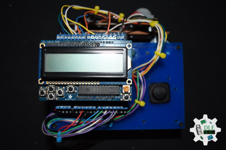
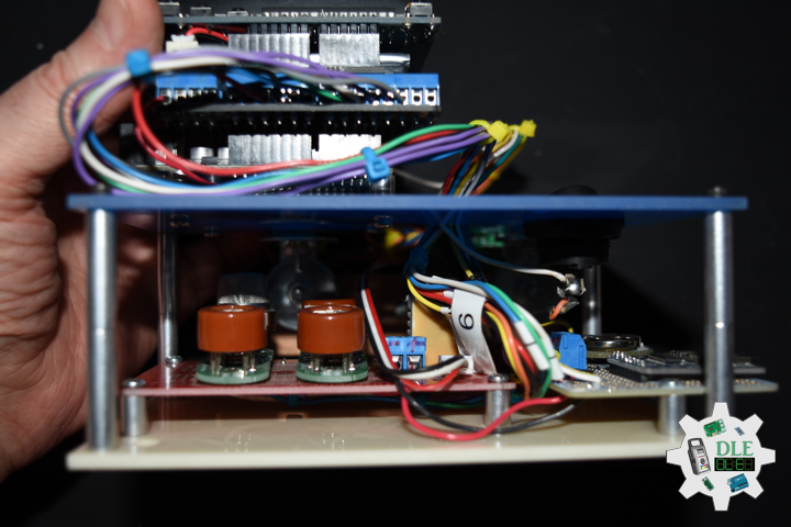
Project #7: RGB LCD Shield – PIR Motion Sensor – Mk03

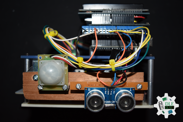
PIR Motion Sensor

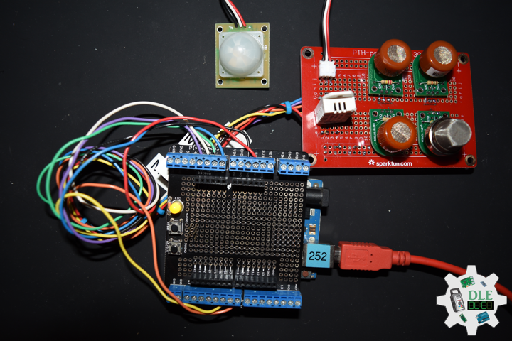
This is a simple to use motion sensor. Power it up and wait 1-2 seconds for the sensor to get a snapshot of the still room. If anything moves after that period, the ‘alarm’ pin will go low.

This unit works great from 5 to 12V (datasheet shows 12V). You can also install a jumper wire past the 5V regulator on board to make this unit work at 3.3V. Sensor uses 1.6mA@3.3V.

The alarm pin is an open collector meaning you will need a pull up resistor on the alarm pin. The open drain setup allows multiple motion sensors to be connected on a single input pin. If any of the motion sensors go off, the input pin will be pulled low.

We’ve finally updated the connector! Gone is the old “odd” connector, now you will find a common 3-pin JST! This makes the PIR Sensor much more accessible for whatever your project may need. Red = Power, White = Ground, and Black = Alarm.

Buzzer

This is a small 12mm round speaker that operates around the audible 2kHz range. You can use these speakers to create simple music or user interfaces.

This is not a true piezoelectric speaker but behaves similarly. Instead of a piezoelectric crystal that vibrates with an electric current, this tiny speaker uses an electromagnet to drive a thin metal sheet. That means you need to use some form of alternating current to get sound. The good news is that this speaker is tuned to respond best with a square wave (e.g. from a microcontroller).

LED

LED Yellow
LED Green

DonLuc1805Mk07

1 x RGB LCD Shield 16×2 Character Display
1 x Arduino UNO – R3
1 x ProtoScrewShield
1 x PIR Motion Sensor
1 x Buzzer
1 x LED Yellow
1 x LED Green
2 x Jumper Wires 2″ M/F
4 x Jumper Wires 3″ M/M
5 x Jumper Wires 6″ M/M
1 x Half-Size Breadboard

Arduino UNO

JST – Digital 6
BUZ – Digital 2
LEY – Digital 1
LEG – Digital 0
VIN – +5V
GND – GND

DonLuc1805Mk07a.ino

// ***** Don Luc *****
// Software Version Information
// Project #7: RGB LCD Shield – PIR Motion Sensor - Mk03
// 5-3.01
// DonLuc1804Mk07 5-3.01
// RGB LCD Shield
// PIR Motion Sensor (JST}

// include the library code:
#include <Adafruit_MCP23017.h>
#include <Adafruit_RGBLCDShield.h>

Adafruit_RGBLCDShield RGBLCDShield = Adafruit_RGBLCDShield();
#define GREEN 0x2

// PIR Motion Sensor (JST}
const int buz = 6;          // Buzzer
const int MOTION_PIN = 2;   // Pin connected to motion detector
const int LED_Yellow = 1;   // LED Yellow
const int LED_Green = 0;    // LED Green

void loop() {

  // PIR Motion Sensor (JST}
  isJST();

  delay(1000);
  
  // Clear
  RGBLCDShield.clear();
  
}

getJST.ino

void isJST(){
  
  int proximity = digitalRead(MOTION_PIN);   // PIR Motion Sensor
  
  if (proximity == LOW) // If the sensor's output goes low, motion is detected
  {

    // Motion Detected
    digitalWrite(buz, HIGH);         // Buzzer High
    digitalWrite(LED_Yellow, HIGH);  // LED Yellow High
    digitalWrite(LED_Green, LOW);    // LED Green Low
    
    // Display
    // Set the cursor to column 0, line 0  
    RGBLCDShield.setCursor(0,0);
    RGBLCDShield.print("Motion Detected!");   // Motion Detected!
    // Set the cursor to column 0, line 1
    RGBLCDShield.setCursor(0, 1);
    RGBLCDShield.print("Buzzer On - Yel");     // Buzzer On
   
  }
  else
  {

    // Motion Off
    digitalWrite(buz, LOW);         // Buzzer Low
    digitalWrite(LED_Yellow, LOW);  // LED Yellow Low
    digitalWrite(LED_Green, HIGH);  // LED Green High
    
    // Display
    // Set the cursor to column 0, line 0  
    RGBLCDShield.setCursor(0,0);
    RGBLCDShield.print("Motion Off!");        // Motion Off!
    // Set the cursor to column 0, line 1
    RGBLCDShield.setCursor(0, 1);
    RGBLCDShield.print("Buzzer Off - Gr");    // "Buzzer Off
          
  }
  
}

setup.ino

void setup() {

  // set up the LCD's number of columns and rows: 
  RGBLCDShield.begin(16, 2);
  RGBLCDShield.setBacklight(GREEN);
  
  // Display
  // Set the cursor to column 0, line 0  
  RGBLCDShield.setCursor(0,0);  
  RGBLCDShield.print("Don Luc");         // Don luc
  // Set the cursor to column 0, line 1
  RGBLCDShield.setCursor(0, 1);
  RGBLCDShield.print("Motion Sensor");   // Motion Sensor

  delay(5000);

  // Clear
  RGBLCDShield.clear();
  
  // PIR Motion Sensor (JST}
  pinMode(buz, OUTPUT);                // Buzzer
  pinMode(MOTION_PIN, INPUT_PULLUP);   // PIR Motion Sensor
  pinMode(LED_Yellow, OUTPUT);         // LED Yellow
  pinMode(LED_Green, OUTPUT);          // LED Green  
      
}

Don Luc

Project #6: MicroView – RHT03 Sensor – Mk07

RHT03 Humidity and Temperature Sensor

The RHT03 (also known by DHT-22) is a low cost humidity and temperature sensor with a single wire digital interface. The sensor is calibrated and doesn’t require extra components so you can get right to measuring relative humidity and temperature.

Features

* 3.3-6V Input
* 1-1.5mA measuring current
* 40-50 uA standby current
* Humidity from 0-100% RH
* -40 – 80 degrees C temperature range
* +-2% RH accuracy
* +-0.5 degrees C

Technical Specification

Model: RHT03
Power supply: 3.3-6V DC
Output signal: Digital signal via MaxDetect 1-wire bus
Sensing element: Polymer humidity capacitor
Operating range: Humidity 0-100%RH; Temperature -40~80C
Accuracy: humidity +-2%RH(Max +-5%RH); Temperature +-0.5C
Resolution or sensitivity: Humidity 0.1%RH; Temperature 0.1C
Repeatability: Humidity +-1%RH; Temperature +-0.2C – Humidity hysteresis – +-0.3%RH
Long-term Stability: +-0.5%RH/year
Interchangeability: Fully interchangeable

DonLuc1805Mk06

1 x MicroView
1 x MicroView – USB Programmer
1 x RHT03
3 x Jumper Wires 3″ M/M
1 x Half-Size Breadboard

MicroView

RHT – PIN 11 – Digital 2
VIN – PIN 15 – +5V
GND – PIN 08 – GND

DonLuc1805Mk06a.ino

// ***** Don Luc *****
// Software Version Information
// 7.01
// DonLuc1804Mk07 7.01
// MicroView
// RHT03 Humidity and Temperature Sensor

// include the library code:
#include <MicroView.h>
#include <SparkFun_RHT03.h>

// RHT Humidity and Temperature Sensor
const int RHT03_DATA_PIN = 2;           // RHT03 data pin Digital 2
RHT03 rht;                              // This creates a RTH03 object, which we'll use to interact with the sensor

void loop() {

  // RHT03 Humidity and Temperature Sensor
  isRHT03();

  delay(1000);
  
  uView.clear(PAGE);  // Erase the memory buffer, the OLED will be cleared
  
}

getRHT.ino

// RHT03 Humidity and Temperature Sensor
void isRHT03(){

  // Call rht.update() to get new humidity and temperature values from the sensor.
  int updateRet = rht.update();
  
  // The humidity(), tempC(), and tempF() functions can be called -- after 
  // a successful update() -- to get the last humidity and temperature
  // value 
  float latestHumidity = rht.humidity();
  float latestTempC = rht.tempC();
  float latestTempF = rht.tempF();

  uView.setFontType(0);  // Set font type 0: Numbers and letters. 10 characters per line (6 lines)
  
  uView.setCursor(0,10); // Humidity
  uView.print( "H : " );
  uView.print( latestHumidity );

  uView.setCursor(0,20); // Temperature *C
  uView.print( "*C: " );
  uView.print( latestTempC );

  uView.setCursor(0,30); // "Temperature *F
  uView.print( "*F: " );
  uView.print( latestTempF );
     
  uView.display();       // Display
   
}

setup.ino

void setup() {

  uView.begin();           // Begin of MicroView
  uView.clear(ALL);        // Erase hardware memory inside the OLED controller
  uView.display();         // Display the content in the buffer memory, by default it is the MicroView logo
  
  delay(1000);
  
  uView.clear(PAGE);       // Erase the memory buffer, the OLED will be cleared.
   
  uView.setFontType(1);    // Set font type 1: Numbers and letters. 7 characters per line (3 lines)
  uView.setCursor(0,20);
  uView.print("Don Luc");  // Don Luc
  uView.display();         // Display
  
  delay(5000);

  uView.clear(PAGE);       // Erase the memory buffer, the OLED will be cleared.

  uView.setFontType(1);    // Set font type 1: Numbers and letters. 7 characters per line (3 lines)
  uView.setCursor(0,20);
  uView.print("RHT03");    // RHT03
  uView.display();         // Display 
  
  delay(5000);
  
  uView.clear(PAGE);       // Erase the memory buffer, the OLED will be cleared
 
  // RHT03 Humidity and Temperature Sensor
  // Call rht.begin() to initialize the sensor and our data pin
  rht.begin(RHT03_DATA_PIN);
    
}

Don Luc
Project #6: MicroView – Accelerometer ADXL335 – Mk06

Accelerometer

An accelerometer is a device that measures proper acceleration. Proper acceleration, being the acceleration (or rate of change of velocity) of a body in its own instantaneous rest frame, is not the same as coordinate acceleration, being the acceleration in a fixed coordinate system. For example, an accelerometer at rest on the surface of the Earth will measure an acceleration due to Earth’s gravity, straight upwards (by definition) of g = 9.81 m/s2. By contrast, accelerometers in free fall (falling toward the center of the Earth at a rate of about 9.81 m/s2) will measure zero.

Triple Axis Accelerometer Breakout – ADXL335

Breakout board for the 3 axis ADXL335 from Analog Devices. This is the latest in a long, proven line of analog sensors – the holy grail of accelerometers. The ADXL335 is a triple axis MEMS accelerometer with extremely low noise and power consumption – only 320uA! The sensor has a full sensing range of +/-3g. There is no on-board regulation, provided power should be between 1.8 and 3.6VDC. Board comes fully assembled and tested with external components installed. The included 0.1uF capacitors set the bandwidth of each axis to 50Hz.

DonLuc1805Mk05

1 x MicroView
1 x MicroView – USB Programmer
1 x Accelerometer ADXL335
5 x Jumper Wires 3″ M/M
1 x Half-Size Breadboard

MicroView

Z-Axis – PIN 07 – Analog A0
Y-Axis – PIN 06 – Analog A1
X-Axis – PIN 05 – Analog A2
VIN – PIN 16 – 3.3V
GND – PIN 08 – GND

DonLuc1805Mk05a.ino

// ***** Don Luc *****
// Software Version Information
// 6.01
// DonLuc1804Mk06 6.01
// MicroView
// Accelerometer ADXL335

// include the library code:
#include <MicroView.h>
#include <ADXL335.h>

// Accelerometer ADXL335
const int pin_x = A0;     // X-Axis
const int pin_y = A1;     // Y-Axis
const int pin_z = A2;     // Z-Axis
const int vin = 16;       // 3.3V
const int gnd = 8;        // GND

ADXL335 accel(pin_x, pin_y, pin_z, vin);

void loop() {

  // Accelerometer ADXL335
  isADXL335();

  delay(500);
  
  uView.clear(PAGE);  // Erase the memory buffer, the OLED will be cleared
  
}

getADXL335.ino

// Accelerometer ADXL335
void isADXL335(){

  // This is required to update the values
  accel.update();

  float rho;
  float phi;
  float theta;  
  
  rho = accel.getRho();
  phi = accel.getPhi();
  theta = accel.getTheta();

  uView.setFontType(0);  // Set font type 0: Numbers and letters. 10 characters per line (6 lines)
  
  uView.setCursor(0,10); // X-Axis
  uView.print( "X: " );
  uView.print( rho );

  uView.setCursor(0,20); // Y-Axis
  uView.print( "Y: " );
  uView.print( phi );

  uView.setCursor(0,30); // Z-Axis
  uView.print( "Z: " );
  uView.print( theta );
     
  uView.display();       // Display
  
}

setup.ino

void setup() {

  uView.begin();           // Begin of MicroView
  uView.clear(ALL);        // Erase hardware memory inside the OLED controller
  uView.display();         // Display the content in the buffer memory, by default it is the MicroView logo
  
  delay(1000);
  
  uView.clear(PAGE);       // Erase the memory buffer, the OLED will be cleared.
   
  uView.setFontType(1);    // Set font type 1: Numbers and letters. 7 characters per line (3 lines)
  uView.setCursor(0,20);
  uView.print("Don Luc");  // Don Luc
  uView.display();         // Display
  
  delay(5000);

  uView.clear(PAGE);       // Erase the memory buffer, the OLED will be cleared.

  uView.setFontType(1);    // Set font type 1: Numbers and letters. 7 characters per line (3 lines)
  uView.setCursor(0,20);
  uView.print("ADXL335");  // ADXL335
  uView.display();         // Display
  
  delay(5000);
  
  uView.clear(PAGE);       // Erase the memory buffer, the OLED will be cleared
 
  // Accelerometer ADXL335
  pinMode(gnd, OUTPUT);    // GND
  pinMode(vin, OUTPUT);    // 3.3V
  digitalWrite(gnd, LOW);
  digitalWrite(vin, HIGH);
  
}

Don Luc
Project #7: RGB LCD Shield – GPS Receiver – Mk02

GPS Receiver

Global Positioning System

The Global Positioning System (GPS), originally Navstar GPS, is a satellite-based radionavigation system owned by the United States government and operated by the United States Air Force. It is a global navigation satellite system that provides geolocation and time information to a GPS receiver anywhere on or near the Earth where there is an unobstructed line of sight to four or more GPS satellites. Obstacles such as mountains and buildings block the relatively weak GPS signals.

The GPS does not require the user to transmit any data, and it operates independently of any telephonic or internet reception, though these technologies can enhance the usefulness of the GPS positioning information. The GPS provides critical positioning capabilities to military, civil, and commercial users around the world. The United States government created the system, maintains it, and makes it freely accessible to anyone with a GPS receiver.

DonLuc1805Mk04

1 x RGB LCD Shield 16×2 Character Display
1 x Arduino UNO – R3
1 x ProtoScrewShield
1 x GPS – GP-20U7

Arduino UNO

Digital 5
GND
3.3V

DonLuc1805Mk04a.ino

// ***** Don Luc *****
// Software Version Information
// 5-4.01
// DonLuc1805Mk04 5-4.01
// RGB LCD Shield
// GPS

// include the library code:
#include <Adafruit_MCP23017.h>
#include <Adafruit_RGBLCDShield.h>
#include <TinyGPS.h>
#include <SoftwareSerial.h>

Adafruit_RGBLCDShield RGBLCDShield = Adafruit_RGBLCDShield();
#define GREEN 0x2

// GPS
#define gpsRXPIN 5
#define gpsTXPIN 4   //this one is unused and doesnt have a conection
SoftwareSerial tGPS(gpsRXPIN, gpsTXPIN);
TinyGPS gps;

// Global variables and functions are declared here, this allows them to be called anywhere
// within the code and is helpful for passing data out of functions. Dont get in the habit \
// of using these though because as your code gets longer its easy to lose track of where
// you are changing these variables and can lead to a headach when a problem arises.
float TargetLat;
float TargetLon;
int Status = 0;

// Function headers can be placed here so that functions can be placed below your setup
// and loop function for a more logical flow of information.
void getGPS( float* lat, float* lon, int* Status);

void loop() {

  RGBLCDShield.clear();

  // Receives NEMA data from GPS receiver and Parses Latitude and longitude data
  // returns information using pointers including info on stagnant data
  // Here we tell it to listen to the tGPS serial object
  // then call the function that will recieve and parse the signal from the GPS reciver
  tGPS.listen();
  getGPS(&TargetLat, &TargetLon, &Status);
  
  // Print status to console to know if you are getting good data or not.
  // No Lock = 0, Old Data(>5 sec old) = 1, Good Data = 2

  // set the cursor to column 0, line 0
  RGBLCDShield.setCursor(0,0);
  RGBLCDShield.print( "Status:" ); 
  RGBLCDShield.print( Status );

  delay(2000);

  RGBLCDShield.clear();
  
  // set the cursor to column 0, line 0
  RGBLCDShield.setCursor(0,0);
  RGBLCDShield.print( "Lon: " );
  RGBLCDShield.print( TargetLon );

  // set the cursor to column 0, line 1
  RGBLCDShield.setCursor(0, 1);
  RGBLCDShield.print( "Lat: " );
  RGBLCDShield.print( TargetLat );

  delay(5000);
    
}

tGPS.ino

/* GPS Vector Pointer Target
   This sketch simiulates any system that has a GPS beacon and has the ability to
   broadcast this information for other systems to pick up. This could be a plane/drone
   a car/rover or even a solar panel on a space elevator climber. This recieves updating GPS
   coordinates and from an attached GPS receiver, parses the incoming NEMA data and
   send that information using an Xbee connection to the base station.
*/

void getGPS( float* lat, float* lon, int* Status)
/* This function switches the softserial pin to the one used for GPS then recieves NEMA data from a GPS
   receiver which is passed into a TinyGPS Object and parsed using its internal functions for $GPRMC info. This function uses
   pointers to pass infomation to pass back to parent function which includes Latitude, longitude,( velocity,
   heading) and the status of the GPS signal. Function call where variables can be nammed whatever they want as long as they have &:
   getGPS(&latitude, &longitude, &Status);
*/
{
  // Initilize pin to receive NEMA (have to do it here because we need to switch between
  // software serial pins (if time permits interrupts could be used)

  // define local variables
  float flat;
  float flon;
  unsigned long fix_age;

  //look for serial data from GPS and loop untill the end of NEMA string
  while (tGPS.available())
  {

    int c = tGPS.read();

    if (gps.encode(c));
    {} 
    
  }

  //Pulled parsed data from gps object
  gps.f_get_position(&flat, &flon, &fix_age);
  *lat = flat;
  *lon = flon;

  // check if data is relavent
  if (fix_age == TinyGPS::GPS_INVALID_AGE)
    //No fix detected;
  {
    *Status = 0;
  }

  else if (fix_age > 5000)
    //Warning: possible stale data!;
  {
    *Status = 1;
  }

  else
    //Data is current;
  {
    *Status = 2;
  }

}

setup.ino

void setup() {

  // set up the LCD's number of columns and rows: 
  RGBLCDShield.begin(16, 2);

  RGBLCDShield.print("Don Luc");
  RGBLCDShield.setBacklight(GREEN);
   // set the cursor to column 0, line 1
  RGBLCDShield.setCursor(0, 1);
  // print the number of seconds since reset:
  RGBLCDShield.print("GPS - GP-20U7"); 

  delay(5000);

  // This function is run before the your program begins to loop, here we define the status
  // of pins that are used for inputs and outputs
  pinMode(gpsRXPIN, INPUT);

  // Next communication begins between the three systems along for the baud rate for each
  // some of these can handle a larger baud rate but you need to make sure they match what
  // they are communicating with
  tGPS.begin(9600);
  Serial.begin(9600);
  
}

Don Luc
Project #6: MicroView – Mk05

MicroView
Project #6 – Mk05

4 x LED

1 x MicroView
1 x MicroView – USB Programmer
1 X Resistor 620 Ohm
1 X Resistor 5 Ohm
1 X Resistor 250 Ohm
1 X Resistor 200 Ohm
1 X 3mm Low Current Red LED – WP710A10LSRD
1 x 3mm Low Current Yellow LED – WP710A10LYD
1 x 3mm Low Current Green LED – WP710A10LGD
1 x 3mm Low Current Red LED – WP710A10LID
9 x Jumper Wires 3″ M/M
1 x Half-Size Breadboard

08 pin – GND
14 pin – 6
13 pin – 5
12 pin – 3
11 pin – 2

DonLuc1804Mk09a.ino

// ***** Don Luc *****
// Software Version Information
// 5.01
// DonLuc1804Mk06 5.01
// MicroView
// 4 x LED

// include the library code:
#include <MicroView.h>

// 4 x LED
int ledPinR = 2;   // select the pin for the LED Red - WP710A10LSRD
int ledPinY = 3;   // select the pin for the LED Yellow - WP710A10LYD
int ledPinG = 5;   // select the pin for the LED Green - WP710A10LGD
int ledPinR1 = 6;   // select the pin for the LED Red - WP710A10LID

void loop() {

  // 4 x LED
  isLED();

  uView.clear(PAGE);
  
}

getLED.ino

void isLED(){

  digitalWrite(ledPinR, HIGH);  // turn the ledPinR on
  digitalWrite(ledPinY, HIGH);  // turn the ledPinY on
  digitalWrite(ledPinG, HIGH);  // turn the ledPinG on
  digitalWrite(ledPinR1, HIGH);  // turn the ledPinR1 on

  uView.setFontType(1);  // set font type 1: Numbers and letters. 7 characters per line (3 lines)
  uView.setCursor(0,20);
  uView.print( "   On" );
  uView.display();

  delay(5000);
  uView.clear(PAGE); 

  digitalWrite(ledPinR, LOW);  // turn the ledPinR off
  digitalWrite(ledPinY, LOW);  // turn the ledPinY off
  digitalWrite(ledPinG, LOW);  // turn the ledPinG off
  digitalWrite(ledPinR1, LOW);  // turn the ledPinR1 off

  uView.setCursor(0,20);
  uView.print( "  Off" );
  uView.display();

  delay(5000);
  uView.clear(PAGE); 

  digitalWrite(ledPinR, HIGH);  // turn the ledPinR on

  uView.setFontType(0);  // set font type 0: Numbers and letters. 10 characters per line (6 lines)
  uView.setCursor(0,20);
  uView.print( "PinR=On" );
  uView.display();

  delay(3000);
  uView.clear(PAGE); 

  digitalWrite(ledPinR, LOW);  // turn the ledPinR off
  digitalWrite(ledPinY, HIGH);  // turn the ledPinY on
  
  uView.setCursor(0,10);
  uView.print( "PinR=Off" );
  uView.display();
 
  uView.setCursor(0,30);
  uView.print( "PinY=On" );
  uView.display();
  
  delay(3000);
  uView.clear(PAGE); 

  digitalWrite(ledPinY, LOW);  // turn the ledPinY off
  digitalWrite(ledPinG, HIGH);  // turn the ledPinG on
  
  uView.setCursor(0,10);
  uView.print( "PinY=Off" );
  uView.display();

  uView.setCursor(0,30);
  uView.print( "PinG=On" );
  uView.display();
  
  delay(3000);
  uView.clear(PAGE); 

  digitalWrite(ledPinG, LOW);  // turn the ledPinG off
  digitalWrite(ledPinR1, HIGH);  // turn the ledPinR1 on
  
  uView.setCursor(0,10);
  uView.print( "PinG=Off" );
  uView.display();

  uView.setCursor(0,30);
  uView.print( "PinR1=On" );
  uView.display();
  
  delay(3000);
  uView.clear(PAGE); 

  digitalWrite(ledPinR, LOW);  // turn the ledPinR off
  digitalWrite(ledPinY, LOW);  // turn the ledPinY off
  digitalWrite(ledPinG, LOW);  // turn the ledPinG off
  digitalWrite(ledPinR1, LOW);  // turn the ledPinR1 off

  uView.setFontType(1); // set font type 1: Numbers and letters. 7 characters per line (3 lines)
  uView.setCursor(0,20);
  uView.print( "Off" );
  uView.display();

  delay(3000);
  uView.clear(PAGE);

}

setup.ino

void setup() {

  uView.begin();       // begin of MicroView
  uView.clear(ALL);    // erase hardware memory inside the OLED controller
  uView.display();     // display the content in the buffer memory, by default it is the MicroView logo
  delay(1000);
  uView.clear(PAGE);   // erase the memory buffer, when next uView.display() is called, the OLED will be cleared.

  uView.setFontType(1); // set font type 1: Numbers and letters. 7 characters per line (3 lines)
  uView.setCursor(0,20);
  uView.print("Don Luc");
  uView.display();
  delay(5000);

  uView.clear(PAGE);     // erase the memory buffer, when next uView.display() is called, the OLED will be cleared.

  uView.setFontType(1);  // set font type 1: Numbers and letters. 7 characters per line (3 lines)
  uView.setCursor(0,20);
  uView.print("4 x LED");
  uView.display();
  delay(5000);
  
  uView.clear(PAGE);

  // ledPinR, ledPinY, ledPinG, ledPinR1
  pinMode(ledPinR, OUTPUT);
  pinMode(ledPinY, OUTPUT);
  pinMode(ledPinG, OUTPUT);
  pinMode(ledPinR1, OUTPUT);  
  
}

Don Luc
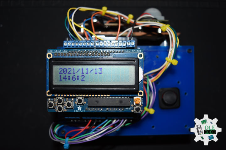
Project #7: RGB LCD Shield – Mk01

RGB LCD Shield
Project #7 – Mk01

ChronoDot

1 x RGB LCD Shield 16×2 Character Display
1 x Arduino Uno – R3
1 x ProtoScrewShield
1 x ChronoDot
4 x Jumper Wires 3″ M/M
1 x Half-Size Breadboard

A5
A4
GND
3.3V

DonLuc1804Mk07a.ino

// ***** Don Luc *****
// Software Version Information
// 1.03
// DonLuc1804Mk07 1.03
// RGB LCD Shield
// ChronoDot

// include the library code:
#include <Wire.h>
#include <Adafruit_MCP23017.h>
#include <Adafruit_RGBLCDShield.h>
#include <RTClib.h>
#include <RTC_DS3231.h>

RTC_DS3231 RTC;

#define SQW_FREQ DS3231_SQW_FREQ_1024     //0b00001000   1024Hz

Adafruit_RGBLCDShield RGBLCDShield = Adafruit_RGBLCDShield();

#define GREEN 0x2

// ChronoDot
char datastr[100];

void loop() {

  RGBLCDShield.clear();

  timeChrono();
   
  delay(2000);  

}

ChronoDot.ino

void setupChrono() {

  RTC.begin();
  
  DateTime now = RTC.now();
  DateTime compiled = DateTime(__DATE__, __TIME__);
  RTC.getControlRegisterData( datastr[0] );  
  
}

void timeChrono() {
 
    DateTime now = RTC.now();
    DateTime isNow (now.unixtime() + 6677 * 86400L + 42500);

    // set the cursor to column 0, line 0
    RGBLCDShield.setCursor(0,0);
    RGBLCDShield.print(isNow.year(), DEC);
    RGBLCDShield.print('/');
    RGBLCDShield.print(isNow.month(), DEC);
    RGBLCDShield.print('/');
    RGBLCDShield.print(isNow.day(), DEC);
    RGBLCDShield.print(' ');
    RGBLCDShield.print(' ');

    // set the cursor to column 0, line 1
    RGBLCDShield.setCursor(0, 1);
    RGBLCDShield.print(isNow.hour(), DEC);
    RGBLCDShield.print(':');
    RGBLCDShield.print(isNow.minute(), DEC);
    RGBLCDShield.print(':');
    RGBLCDShield.print(isNow.second(), DEC);
    RGBLCDShield.print(' ');
    RGBLCDShield.print(' ');
    
}

setup.ino

void setup() {

  // set up the LCD's number of columns and rows: 
  RGBLCDShield.begin(16, 2);

  RGBLCDShield.print("Don Luc");
  RGBLCDShield.setBacklight(GREEN);
   // set the cursor to column 0, line 1
  RGBLCDShield.setCursor(0, 1);
  // print the number of seconds since reset:
  RGBLCDShield.print("ChronoDot"); 

  delay(5000);

  // ChronoDot
  setupChrono();
  
  delay(1500); //wait for the sensor to be ready 
  
}

Don Luc

Project #6: MicroView – Mk04

MicroView
Project #6 – Mk04

Trimpot – LED

1 x MicroView
1 x MicroView – USB Programmer
1 X Trimpot 10K with Knob
1 X Resistor 2.55k Ohm
1 X 3MM Low Current Red LED
6 x Jumper Wires 3″ M/M
1 x Half-Size Breadboard

05 pin – A2
08 pin – GND
11 pin – 2
15 pin – +5V

DonLuc1804Mk06d.ino

// ***** Don Luc *****
// Software Version Information
// 3.01
// DonLuc1804Mk06 4.04
// MicroView
// Trimpot - LED

// include the library code:
#include <MicroView.h>

// Potentiometer
int potPin = A2;    // select the input pin for the potentiometer
int ledPin = 2;   // select the pin for the LED
int potPot = 0;
String cap = "";

void loop() {

  // Potentiometer
  isCap();

  delay(500);
  uView.clear(PAGE);
  
}

getPot.ino

void isCap(){

    potPot = analogRead(potPin);    // read the value from the sensor
    cap = "Pot: ";
    cap.concat(potPot);
    
    uView.setFontType(0);
    uView.setCursor(0,20);
    uView.print( cap );
    uView.display();
    
}

setup.ino

void setup() {

  uView.begin();       // begin of MicroView
  uView.clear(ALL);    // erase hardware memory inside the OLED controller
  uView.display();     // display the content in the buffer memory, by default it is the MicroView logo
  delay(1000);
  uView.clear(PAGE);   // erase the memory buffer, when next uView.display() is called, the OLED will be cleared.

  uView.setFontType(1);
  uView.setCursor(0,20);
  uView.print("Don Luc");
  uView.display();
  delay(5000);

  uView.clear(PAGE);   // erase the memory buffer, when next uView.display() is called, the OLED will be cleared.

  uView.setFontType(0);
  uView.setCursor(0,20);
  uView.print("TrimpotLED");
  uView.display();
  delay(5000);
  
  uView.clear(PAGE);

  // ledPin
  pinMode(ledPin, OUTPUT);
  digitalWrite(ledPin, HIGH);  // turn the ledPin on

}

Don Luc

Project #6: MicroView – Mk03

MicroView
Project #6 – Mk03

1 x MicroView
1 x DS18S20
1 x Resistor 1.65k Ohm
3 x Jumper Wires 3″ M/M

08 pin – GND
11 pim – 2
15 pin – +5V

DonLuc1804Mk05b.ino

// ***** Don Luc *****
// Software Version Information
// 3.01
// DonLuc1804Mk05 3.01
// MicroView
// OneWire
// DS18S20

#include <MicroView.h>
#include <OneWire.h>
// Temperature chip i/o
int DS18S20_Pin = 2; //DS18S20 Signal pin on digital 2
OneWire ds(DS18S20_Pin);  // on digital pin 2
float temperature = 0;
String tempZ = "";

void loop() {

  // Temperature chip i/o
  temperatu();
  isTe();
      
	uView.setFontType(1);
	uView.setCursor(0,20);
	uView.print("Don Luc");
	uView.display();
	delay(1000);
  
	uView.clear(PAGE);
	
}

getTemperature.ino

float getTemp() {
  
  //returns the temperature from one DS18S20 in DEG Celsius
  byte data[12];
  byte addr[8];
 
  if ( !ds.search(addr)) {
      //no more sensors on chain, reset search
      ds.reset_search();
      return -1001;
  }
 
  if ( OneWire::crc8( addr, 7) != addr[7]) {
      return -1002;
  }
 
  if ( addr[0] != 0x10 && addr[0] != 0x28) {
      return -1003;
  }
 
  ds.reset();
  ds.select(addr);
  ds.write(0x44,1); // start conversion, with parasite power on at the end
 
  byte present = ds.reset();
  ds.select(addr);    
  ds.write(0xBE); // Read Scratchpad
 
  
  for (int i = 0; i < 9; i++) { // we need 9 bytes
    data[i] = ds.read();
  }
  
  ds.reset_search();
  
  byte MSB = data[1];
  byte LSB = data[0];
 
  float tempRead = ((MSB << 8) | LSB); //using two's compliment
  float TemperatureSum = tempRead / 16;
  
  return TemperatureSum;
 
}
 
void temperatu(){
  
  temperature = getTemp();
 
}
 
void isTe() {

  tempZ = "";
  uView.setFontType(1);
  uView.setCursor(0,10);
  uView.print("Celsius");
  uView.setCursor(0,30);  
  tempZ.concat(temperature);
  tempZ.concat("C");
  uView.print( tempZ );
  uView.display();
  delay(5000);

  uView.clear(PAGE);
  
}

setup.ino

void setup() {
  
  uView.begin();       // begin of MicroView
  uView.clear(ALL);    // erase hardware memory inside the OLED controller
  uView.display();     // display the content in the buffer memory, by default it is the MicroView logo
  delay(1000);
  uView.clear(PAGE);   // erase the memory buffer, when next uView.display() is called, the OLED will be cleared.

  uView.setFontType(1);
  uView.setCursor(0,20);
  uView.print("Don Luc");
  uView.display();
  delay(5000);

  uView.clear(PAGE);   // erase the memory buffer, when next uView.display() is called, the OLED will be cleared.

  uView.setFontType(1);
  uView.setCursor(0,20);
  uView.print("OneWire");
  uView.display();
  delay(5000);
  
  uView.clear(PAGE); 

  uView.setFontType(1);
  uView.setCursor(0,20);
  uView.print("DS18S20");
  uView.display();
  delay(5000);
  
  uView.clear(PAGE);
   
}

Don Luc

Project #6: MicroView – Mk02

DonLuc1804Mk04a.ino

// ***** Don Luc *****
// Software Version Information
// 2.01
// DonLuc1804Mk04 2.01
// MicroView

#include <MicroView.h>
#include <Time.h>
#include <TimeLib.h>
// This is the radius of the clock:
#define CLOCK_SIZE 23
// Use these defines to set the clock's begin time
#define HOUR 9
#define MINUTE 00
#define SECOND 00
#define DAY 9
#define MONTH 4
#define YEAR 2018
// LCD W/H
const uint8_t maxW = uView.getLCDWidth();
const uint8_t midW = maxW/2;
const uint8_t maxH = uView.getLCDHeight();
const uint8_t midH = maxH/2;
// Clock
long zzz = 0;
static boolean firstDraw = false;
static unsigned long mSec = millis() + 1000;
static float degresshour, degressmin, degresssec, hourx, houry, minx, miny, secx, secy;
  
void loop() {

  drawFace();
  
  zzz = 0;
  while(zzz < 5000)
  {

     drawTime();
     zzz++;
     
  }
  
  uView.clear(PAGE);
  
  firstDraw = false;
  
  uView.setFontType(0);
  uView.setCursor(0,20);
  uView.print("09/04/2018");
  uView.display();
  delay(5000);
  
  uView.clear(PAGE);

}

drawFace.ino

void drawFace()
{

  // Draw the clock face. That includes the circle outline and
  // the 12, 3, 6, and 9 text.
  uView.setFontType(0); // set font type 0 (Smallest)
  
  uint8_t fontW = uView.getFontWidth();
  uint8_t fontH = uView.getFontHeight();
  
  //uView.setCursor(27, 0); // points cursor to x=27 y=0
  uView.setCursor(midW-fontW-1, midH-CLOCK_SIZE+1);
  uView.print(12);  // Print the "12"
  uView.setCursor(midW-(fontW/2)-1, midH+CLOCK_SIZE-fontH-1);
  uView.print(6);  // Print the "6"
  uView.setCursor(midW-CLOCK_SIZE+1, midH-fontH/2);
  uView.print(9);  // Print the "9"
  uView.setCursor(midW+CLOCK_SIZE-fontW-2, midH-fontH/2);
  uView.print(3);  // Print the "3"
  uView.circle(midW-1, midH-1, CLOCK_SIZE);
  
  //Draw the clock
  uView.display();
  
}

drawTime.ino

void drawTime()
{
   
  // If mSec
  if (mSec != (unsigned long)second()) 
  {
    // First time draw requires extra line to set up XOR's:
    if (firstDraw) 
    {
      uView.line(midW, midH, 32 + hourx, 24 + houry, WHITE, XOR);
      uView.line(midW, midH, 32 + minx, 24 + miny, WHITE, XOR);
      uView.line(midW, midH, 32 + secx, 24 + secy, WHITE, XOR);
    }
    // Calculate hour hand degrees:
    degresshour = (((hour() * 360) / 12) + 270) * (PI / 180);
    // Calculate minute hand degrees:
    degressmin = (((minute() * 360) / 60) + 270) * (PI / 180);
    // Calculate second hand degrees:
    degresssec = (((second() * 360) / 60) + 270) * (PI / 180);

    // Calculate x,y coordinates of hour hand:
    hourx = cos(degresshour) * (CLOCK_SIZE / 2.5);
    houry = sin(degresshour) * (CLOCK_SIZE / 2.5);
    // Calculate x,y coordinates of minute hand:
    minx = cos(degressmin) * (CLOCK_SIZE / 1.4);
    miny = sin(degressmin) * (CLOCK_SIZE / 1.4);
    // Calculate x,y coordinates of second hand:
    secx = cos(degresssec) * (CLOCK_SIZE / 1.1);
    secy = sin(degresssec) * (CLOCK_SIZE / 1.1);

    // Draw hands with the line function:
    uView.line(midW, midH, midW+hourx, midH+houry, WHITE, XOR);
    uView.line(midW, midH, midW+minx, midH+miny, WHITE, XOR);
    uView.line(midW, midH, midW+secx, midH+secy, WHITE, XOR);
    
    // Set firstDraw flag to true, so we don't do it again.
    firstDraw = true;
    
    // Actually draw the hands with the display() function.
    uView.display();
    
  }

}

setup.ino

void setup() {

  // Set the time in the time library:
  setTime(HOUR, MINUTE, SECOND, DAY, MONTH, YEAR);
 
  uView.begin();       // begin of MicroView
  uView.clear(ALL);    // erase hardware memory inside the OLED controller
  uView.display();     // display the content in the buffer memory, by default it is the MicroView logo
  delay(1000);
  uView.clear(PAGE);   // erase the memory buffer, when next uView.display() is called, the OLED will be cleared.

  uView.setFontType(1);
  uView.setCursor(0,20);
  uView.print("Don Luc");
  uView.display();
  delay(5000);
  
  uView.clear(PAGE);

  uView.display();  // display the content in the buffer

  // Draw clock face (circle outline & text):
  drawFace();
  
}

Don Luc

Project #6: MicroView – Mk01

DonLuc1804Mk03b.ino

// ***** Don Luc *****
// Software Version Information
// 1.01
// DonLuc1804Mk03 1.01
// MicroView

#include <MicroView.h>

void loop() {

	uView.setFontType(0);
	uView.setCursor(0,20);
	uView.print("  Don Luc  ");
	uView.display();
	delay(5000);

	uView.clear(PAGE);

	uView.setFontType(1);
	uView.setCursor(0,20);
	uView.print("Don Luc");
	uView.display();
	delay(5000);
  
	uView.clear(PAGE);
	
}

setup.ino

void setup() {
  
  uView.begin();       // begin of MicroView
  uView.clear(ALL);    // erase hardware memory inside the OLED controller
  uView.display();     // display the content in the buffer memory, by default it is the MicroView logo
  delay(1000);
  uView.clear(PAGE);   // erase the memory buffer, when next uView.display() is called, the OLED will be cleared.
  
}

MicroView
Project #6 – Mk01

Don Luc

Categories
Archives