Microcontrollers
Microcontrollers
Project #29 – DFRobot – FireBeetle 2 ESP32-E – Mk01
——
#DonLucElectronics #DonLuc #DFRobot #FireBeetle2ESP32E #ESP32 #Arduino #Project #Fritzing #Programming #Electronics #Microcontrollers #Consultant
——
——
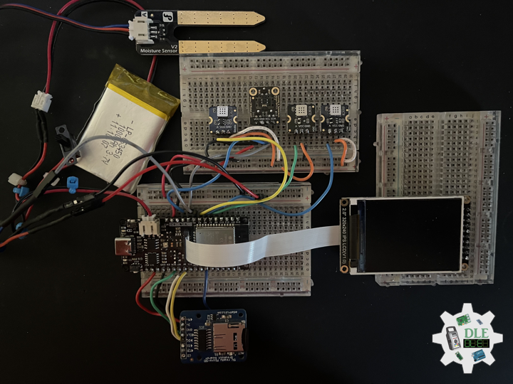
——
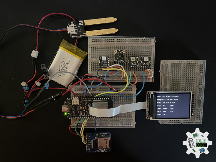
——
——
——
FireBeetle 2 ESP32-E
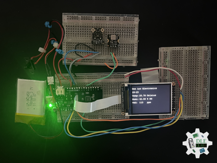
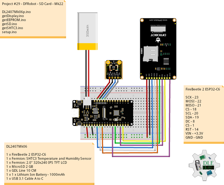
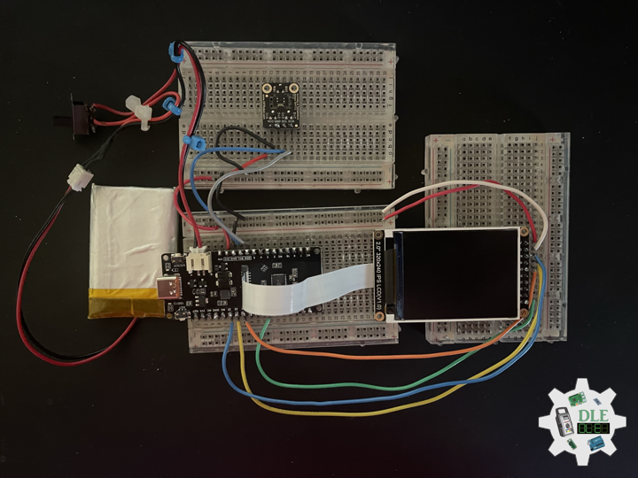
FireBeetle 2 ESP32-E, specially designed for IoT, is an ESP-WROOM-32E-based main controller board with dual-core chips. It supports WiFi and Bluetooth dual-mode communication and features a small size, ultra-low power consumption, on-board charging circuit, and easy-to-use interface, which can be conveniently used for smart home IoT, industrial IoT applications, and wearable devices, and so on. You can easily create your own IoT smart home system when connecting it with an IoT platform like IFTTT. FireBeetle 2 ESP32-E supports Arduino programming.
- Compatible with DFRobot FireBeetle V2 Series
- Small Size of 25.4 mm × 60 mm
- ESP32 Dual-core low power maincontroller, WiFi+BT4.0
- GDI Display Port, say to connect
- Onboard Charging Circuit and PH2.0 li-ion Battery Port
- Operating Voltage: 3.3 Volt
- Input Voltage: 3.3 Volt -5.5 Volt (Support USB Charging)
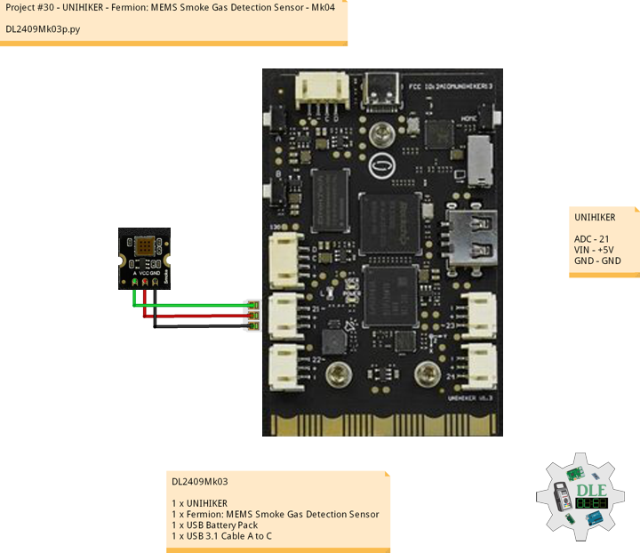
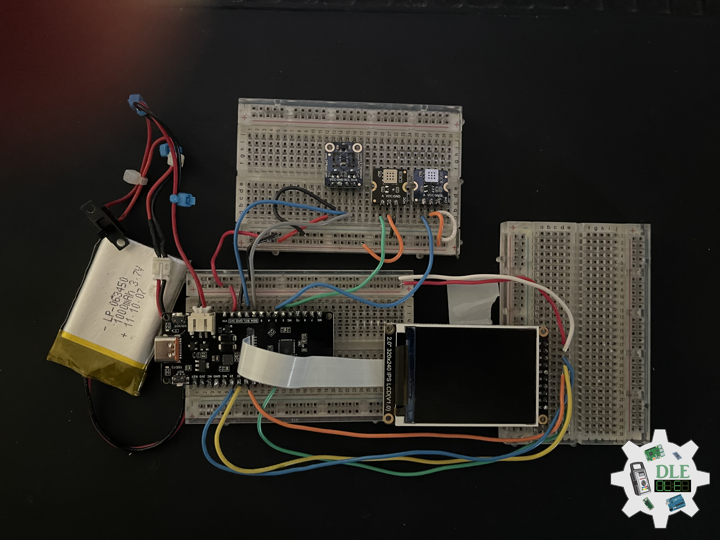
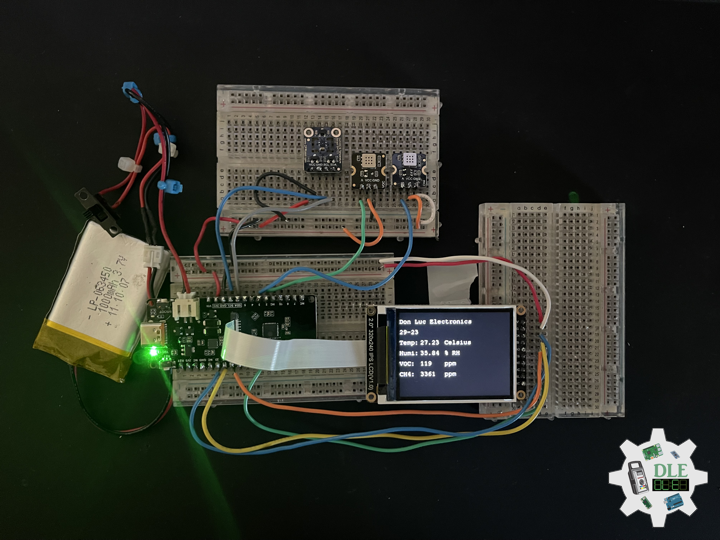
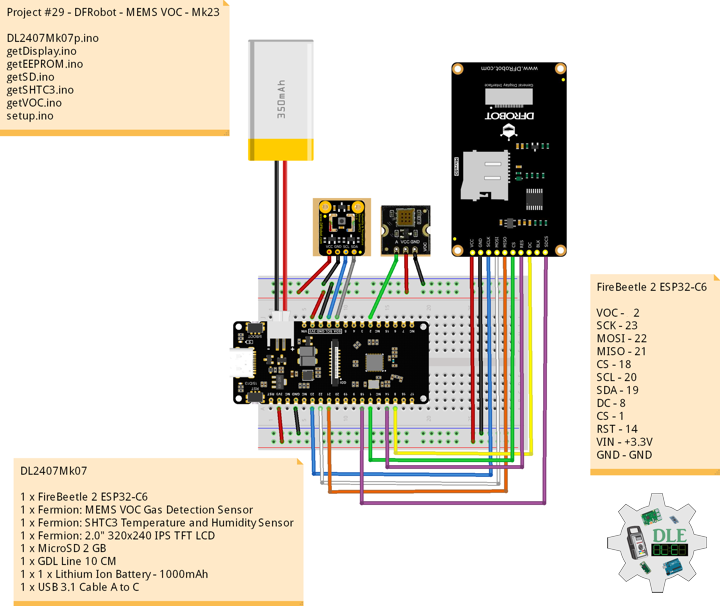
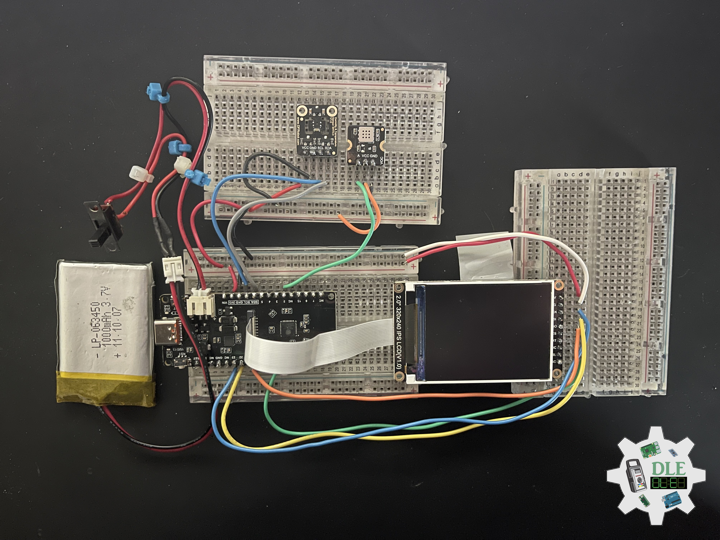
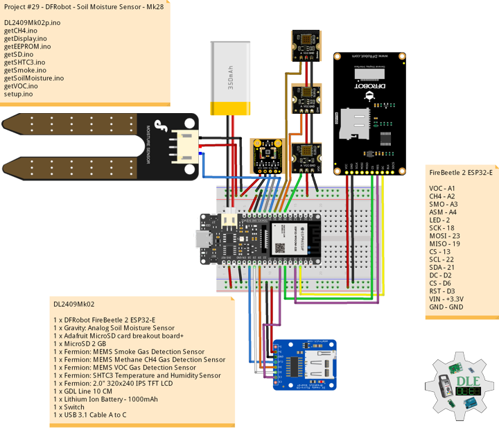
DL2402Mk01
1 x DFRobot FireBeetle 2 ESP32-E
1 x 1 x Lithium Ion Battery – 1000mAh
1 x USB 3.1 Cable A to C
DFRobot FireBeetle 2 ESP32-E
LED – 2
VIN – +3.3V
GND – GND
——
DL2402Mk01p.ino
/****** Don Luc Electronics © ****** Software Version Information Project #29 - DFRobot - FireBeetle 2 ESP32-E - Mk01 29-01 DL2402Mk01p.ino 1 x DFRobot FireBeetle 2 ESP32-E 1 x 1 x Lithium Ion Battery - 1000mAh 1 x USB 3.1 Cable A to C */ // Include the Library Code // Define LED int iLED = 2; // Software Version Information String sver = "29-01"; void loop() { // Outputting high, the LED turns on digitalWrite(iLED, HIGH); // Delay 1 Second delay(1000); // Outputting low, the LED turns off digitalWrite(iLED, LOW); // Delay 1 Second delay(1000); }
setup.ino
// Setup void setup() { // Initialize digital pin iLED as an output pinMode(iLED, OUTPUT); // Delay 5 Second delay( 5000 ); }
——
People can contact us: https://www.donluc.com/?page_id=1927
Teacher, Instructor, E-Mentor, R&D and Consulting
- Programming Language
- Single-Board Microcontrollers (PIC, Arduino, Raspberry Pi, Arm, Silicon Labs, Espressif, Etc…)
- IoT
- Wireless (Radio Frequency, Bluetooth, WiFi, Etc…)
- Robotics
- Automation
- Camera and Video Capture Receiver Stationary, Wheel/Tank and Underwater Vehicle
- Unmanned Vehicles Terrestrial and Marine
- Machine Learning
- Artificial Intelligence (AI)
- RTOS
- eHealth Sensors, Biosensor, and Biometric
- Research & Development (R & D)
- Consulting
Follow Us
Luc Paquin – Curriculum Vitae – 2024
https://www.donluc.com/luc/
Web: https://www.donluc.com/
Facebook: https://www.facebook.com/neosteam.labs.9/
YouTube: https://www.youtube.com/@thesass2063
Twitter: https://twitter.com/labs_steam
Pinterest: https://www.pinterest.com/NeoSteamLabs/
Instagram: https://www.instagram.com/neosteamlabs/
Don Luc
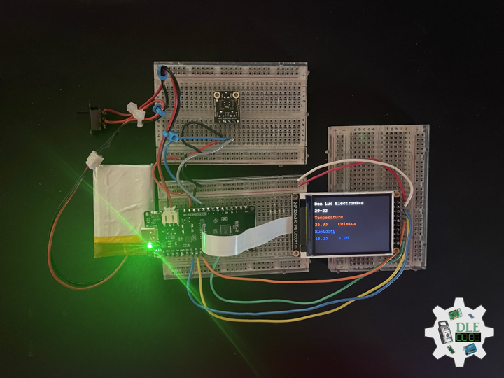
Project #28 – Sensors – PIR Motion Sensor – Mk13
——
#DonLucElectronics #DonLuc #Sensors #PIR #Adafruit #SparkFun #Pololu #Arduino #Project #Fritzing #Programming #Electronics #Microcontrollers #Consultant
——
——
——
——
PIR Motion Sensor (JST)
This is a simple to use motion sensor. Power it up and wait 1-2 seconds for the sensor to get a snapshot of the still room. If anything moves after that period, the “Alarm” pin will go low. This unit works great from 5 to 12 Volt. The alarm pin is an open collector meaning you will need a pull up resistor on the alarm pin. The open drain setup allows multiple motion sensors to be connected on a single input pin. If any of the motion sensors go off, the input pin will be pulled low.
At their most fundamental level, PIR sensor’s are infrared-sensitive light detectors. By monitoring light in the infrared spectrum, PIR sensors can sense subtle changes in temperature across the area they’re viewing. When a human or some other object comes into the PIR’s field-of-view, the radiation pattern changes, and the PIR interprets that change as movement. All that’s left for us to connect is three pins: power, ground, and the output signal.
DL2401Mk02
1 x SparkFun Thing Plus – ESP32 WROOM
1 x DS3231 Precision RTC FeatherWing
1 x PIR Motion Sensor
1 x Pololu 5V Step-Up Voltage Regulator U1V10F5
1 x Rocker Switch – SPST
1 x Resistor 10K Ohm
1 x CR1220 3V Lithium Coin Cell Battery
1 x 1 x Lithium Ion Battery – 1000mAh
1 x Terminal Block Breakout FeatherWing
1 x SparkFun Cerberus USB Cable
SparkFun Thing Plus – ESP32 WROOM
LED – LED_BUILTIN
SDA – Digital 23
SCL – Digital 22
SW1 – Digital 21
PIR – Digital 14
VIN – +3.3V
VIN – +5V
GND – GND
——
DL2401Mk01p.ino
/****** Don Luc Electronics © ****** Software Version Information Project #28 - Sensors - PIR Motion Sensor - Mk13 28-13 DL2401Mk01p.ino 1 x SparkFun Thing Plus - ESP32 WROOM 1 x DS3231 Precision RTC FeatherWing 1 x PIR Motion Sensor 1 x Pololu 5V Step-Up Voltage Regulator U1V10F5 1 x Rocker Switch - SPST 1 x Resistor 10K Ohm 1 x Lithium Ion Battery - 1000mAh 1 x CR1220 3V Lithium Coin Cell Battery 1 x Terminal Block Breakout FeatherWing 1 x SparkFun Cerberus USB Cable */ // Include the Library Code // Bluetooth LE keyboard #include <BleKeyboard.h> // Two Wire Interface (TWI/I2C) #include <Wire.h> // Serial Peripheral Interface #include <SPI.h> // DS3231 Precision RTC #include <RTClib.h> // Bluetooth LE Keyboard BleKeyboard bleKeyboard; String sKeyboard = ""; // Send Size byte sendSize = 0; // DS3231 Precision RTC RTC_DS3231 rtc; String dateRTC = ""; String timeRTC = ""; // PIR Motion // Motion detector const int iMotion = 14; // Proximity int proximity = LOW; String Det = ""; // The number of the Rocker Switch pin int iSwitch = 21; // Variable for reading the button status int SwitchState = 0; // Software Version Information String sver = "28-13"; void loop() { // Date and Time RTC isRTC (); // isPIR Motion isPIR(); // Read the state of the Switch value: SwitchState = digitalRead(iSwitch); // Check if the button is pressed. If it is, the SwitchState is HIGH: if (SwitchState == HIGH) { // Bluetooth LE Keyboard isBluetooth(); } // Delay 1 Second delay(1000); }
getBleKeyboard.ino
// Ble Keyboard // Bluetooth // isBluetooth void isBluetooth() { // ESP32 BLE Keyboard if(bleKeyboard.isConnected()) { // Send Size Length sendSize = sKeyboard.length(); // Send Size, charAt for(byte i = 0; i < sendSize+1; i++){ // Write bleKeyboard.write(sKeyboard.charAt(i)); delay(50); } bleKeyboard.write(KEY_RETURN); } }
getPIR.ino
// PIR Motion // Setup PIR void setupPIR() { // Setup PIR Montion pinMode(iMotion, INPUT_PULLUP); } // isPIR Motion void isPIR() { // Proximity proximity = digitalRead(iMotion); if (proximity == LOW) { // PIR Motion Sensor's LOW, Motion is detected Det = "Motion Yes"; } else { // PIR Motion Sensor's HIGH Det = "No"; } sKeyboard = sKeyboard + String(Det) + "|*"; }
getRTC.ino
// Date & Time // DS3231 Precision RTC void isSetupRTC() { // DS3231 Precision RTC if (! rtc.begin()) { //Serial.println("Couldn't find RTC"); //Serial.flush(); while (1) delay(10); } if (rtc.lostPower()) { //Serial.println("RTC lost power, let's set the time!"); // When time needs to be set on a new device, or after a power loss, the // following line sets the RTC to the date & time this sketch was compiled rtc.adjust(DateTime(F(__DATE__), F(__TIME__))); // This line sets the RTC with an explicit date & time, for example to set // January 21, 2014 at 3am you would call: //rtc.adjust(DateTime(2023, 8, 10, 11, 0, 0)); } } // Date and Time RTC void isRTC () { // Date and Time dateRTC = ""; timeRTC = ""; DateTime now = rtc.now(); // Date dateRTC = now.year(), DEC; dateRTC = dateRTC + "/"; dateRTC = dateRTC + now.month(), DEC; dateRTC = dateRTC + "/"; dateRTC = dateRTC + now.day(), DEC; // Time timeRTC = now.hour(), DEC; timeRTC = timeRTC + ":"; timeRTC = timeRTC + now.minute(), DEC; timeRTC = timeRTC + ":"; timeRTC = timeRTC + now.second(), DEC; // bleKeyboard sKeyboard = "SEN|" + sver + "|" + String(dateRTC) + "|" + String(timeRTC) + "|"; }
setup.ino
// Setup void setup() { // Give display time to power on delay(100); // Bluetooth LE keyboard bleKeyboard.begin(); // Wire - Inialize I2C Hardware Wire.begin(); // Give display time to power on delay(100); // Date & Time RTC // DS3231 Precision RTC isSetupRTC(); // Give display time to power on delay(100); // PIR Motion // Setup PIR setupPIR(); // Initialize the Switch pin as an input pinMode(iSwitch, INPUT); // Initialize digital pin LED_BUILTIN as an output pinMode(LED_BUILTIN, OUTPUT); // Turn the LED on HIGH digitalWrite(LED_BUILTIN, HIGH); // Delay 5 Second delay( 5000 ); }
——
People can contact us: https://www.donluc.com/?page_id=1927
Teacher, Instructor, E-Mentor, R&D and Consulting
- Programming Language
- Single-Board Microcontrollers (PIC, Arduino, Raspberry Pi, Arm, Silicon Labs, Espressif, Etc…)
- IoT
- Wireless (Radio Frequency, Bluetooth, WiFi, Etc…)
- Robotics
- Automation
- Camera and Video Capture Receiver Stationary, Wheel/Tank and Underwater Vehicle
- Unmanned Vehicles Terrestrial and Marine
- Machine Learning
- Artificial Intelligence (AI)
- RTOS
- eHealth Sensors, Biosensor, and Biometric
- Research & Development (R & D)
- Consulting
Follow Us
Luc Paquin – Curriculum Vitae – 2024
https://www.donluc.com/luc/
Web: https://www.donluc.com/
Facebook: https://www.facebook.com/neosteam.labs.9/
YouTube: https://www.youtube.com/@thesass2063
Twitter: https://twitter.com/labs_steam
Pinterest: https://www.pinterest.com/NeoSteamLabs/
Instagram: https://www.instagram.com/neosteamlabs/
Don Luc
Project #05: Lamps – NeoPixels – Mk02
——
#DonLucElectronics #DonLuc #Lamps #NeoPixels #Keyboard #Adafruit #SparkFun #Arduino #Project #Fritzing #Programming #Electronics #Microcontrollers #Consultant
——
——
——
——
——
NeoPixels
The WS2812 Integrated Light Source, or NeoPixel in Adafruit parlance, is the latest advance in the quest for a simple, scalable and affordable full-color LED. Red, green and blue LEDs are integrated alongside a driver chip into a tiny surface-mount package controlled through a single wire. They can be used individually, chained into longer strings or assembled into still more interesting form-factors.
NeoPixels don’t just light up on their own; they require a microcontroller, such as Arduino, and some programming. We provide some sample code to get you started. To create your own effects and animation, you’ll need some programming practice. If this is a new experience, work through some of the beginning Arduino tutorials to get a feel for the language.
NeoPixel Stick – 8 x 5050 RGB LED
Make your own little LED strip arrangement with this stick of NeoPixel LEDs. We crammed 8 of the tiny 5050 smart RGB LEDs onto a PCB with mounting holes and a chainable design. Use only one microcontroller pin to control as many as you can chain together. Each LED is addressable as the driver chip is inside the LED. Each one has constant current drive so the color will be very consistent even if the voltage varies, and no external choke resistors are required making the design slim. Power the whole thing with 5VDC and you’re ready to rock. The LEDs are “Chainable” by connecting the output of one stick into the input of another. There is a single data line with a very timing-specific protocol.
DL2401Mk01
1 x Arduino Pro Mini 328 – 3.3V/8MHz
2 x NeoPixel Stick – 8 x 5050 RGB LED
2 x Rotary Potentiometer – 10k Ohm
1 x Potentiometer Knob – Soft Touch T18 – Blue
1 x Potentiometer Knob – Soft Touch T18 – Red
1 x Mountable Slide Switch
1 x SparkFun USB Mini-B Breakout
1 x Enclosure
1 x SparkFun Cerberus USB Cable
Arduino Pro Mini 328 – 3.3V/8MHz
NPX – Digital 8
BRI – Analog A0
COL – Analog A3
VIN – +3.3V
VIN – +5V
GND – GND
——
DL2401Mk01p.ino
/****** Don Luc Electronics © ****** Software Version Information Project #05: Lamps - NeoPixels - Mk02 05-02 DL2401Mk01p.ino 1 x Arduino Pro Mini 328 - 3.3V/8MHz 2 x NeoPixel Stick - 8 x 5050 RGB LED 2 x Rotary Potentiometer - 10k Ohm 1 x Potentiometer Knob - Soft Touch T18 - Blue 1 x Potentiometer Knob - Soft Touch T18 - Red 1 x Mountable Slide Switch 1 x SparkFun USB Mini-B Breakout 1 x Enclosure 1 x SparkFun Cerberus USB Cable */ // Include the Library Code // NeoPixel #include <Adafruit_NeoPixel.h> // NeoPixels #define PIN 8 // How many NeoPixels are attached to the Arduino => 16 #define NUMPIXELS 16 Adafruit_NeoPixel pixels = Adafruit_NeoPixel(NUMPIXELS, PIN, NEO_GRB + NEO_KHZ800); // Color // Red int red = 0; // Green int green = 0; // Blue int blue = 0; // 2 x Panel Mount 1K potentiometer // Brighten const int iSensorBrighten = A0; int BrightenValue = 0; int sensorMin = 1023; // minimum sensor value int sensorMax = 0; // maximum sensor value // Color const int iSensorColor = A3; int y = 0; int ColorVal = 0; // Software Version Information String sver = "05-02"; void loop() { // Color isRangeColor(); // Brighten isNeopix(); }
getNeopix.ino
// Neopix void isNeopix() { for(int i=0; i<NUMPIXELS; i++){ // Neopix BrightenValue = analogRead( iSensorBrighten ); // Apply the calibration to the sensor reading BrightenValue = map(BrightenValue, sensorMin, sensorMax, 0, 255); // In case the sensor value is outside the range seen during calibration BrightenValue = constrain(BrightenValue, 0, 255); pixels.setBrightness( BrightenValue ); // The pixels.Color takes RGB values, from 0,0,0 up to 255,255,255 pixels.setPixelColor(i, pixels.Color(red,green,blue)); // This sends the updated pixel color to the hardware pixels.show(); } } // Range Color void isRangeColor() { // Range Color ColorVal = analogRead( iSensorColor ); y = (ColorVal / 127); switch ( y ) { case 0: // White red = 255; green = 255; blue = 255; break; case 1: // Yellow red = 255; green = 255; blue = 0; isNeopix(); break; case 2: // Pink red = 255; green = 153; blue = 203; isNeopix(); break; case 3: // Blue red = 0; green = 102; blue = 204; isNeopix(); isNeopix(); break; case 4: // Green red = 0; green = 255; blue = 0; isNeopix(); break; case 5: // Orange red = 255; green = 102; blue = 0; isNeopix(); break; case 6: // Violet red = 204; green = 102; blue = 204; isNeopix(); break; case 7: // Red red = 255; green = 0; blue = 0; isNeopix(); break; } }
setup.ino
// Setup void setup() { // This initializes the NeoPixel library pixels.begin(); delay(50); }
——
People can contact us: https://www.donluc.com/?page_id=1927
Teacher, Instructor, E-Mentor, R&D and Consulting
- Programming Language
- Single-Board Microcontrollers (PIC, Arduino, Raspberry Pi, Arm, Silicon Labs, Espressif, Etc…)
- IoT
- Wireless (Radio Frequency, Bluetooth, WiFi, Etc…)
- Robotics
- Automation
- Camera and Video Capture Receiver Stationary, Wheel/Tank and Underwater Vehicle
- Unmanned Vehicles Terrestrial and Marine
- Machine Learning
- Artificial Intelligence (AI)
- RTOS
- eHealth Sensors, Biosensor, and Biometric
- Research & Development (R & D)
- Consulting
Follow Us
Luc Paquin – Curriculum Vitae – 2024
https://www.donluc.com/luc/
Web: https://www.donluc.com/
Facebook: https://www.facebook.com/neosteam.labs.9/
YouTube: https://www.youtube.com/@thesass2063
Twitter: https://twitter.com/labs_steam
Pinterest: https://www.pinterest.com/NeoSteamLabs/
Instagram: https://www.instagram.com/neosteamlabs/
Don Luc
Teacher, Instructor, E-Mentor, R&D and Consulting
——
#DonLucElectronics #DonLuc #Teacher #Instructor #EMentor #RD #Project #Fritzing #Programming #Electronics #Microcontrollers #Consultant
——
——
Teacher, Instructor, E-Mentor, R&D and Consulting
- Programming Language
- Single-Board Microcontrollers (PIC, Arduino, Raspberry Pi, Arm, Silicon Labs, Espressif, Etc…)
- IoT
- Wireless (Radio Frequency, Bluetooth, WiFi, Etc…)
- Robotics
- Automation
- Camera and Video Capture Receiver Stationary, Wheel/Tank and Underwater Vehicle
- Unmanned Vehicles Terrestrial and Marine
- Machine Learning
- Artificial Intelligence (AI)
- RTOS
- eHealth Sensors, Biosensor, and Biometric
- Research & Development (R & D)
- Consulting
I am a highly skilled programming language, microcontrollers, IoT, robotics and etc; with over 45 years of experience in various industries. I graduated from McGill University, Montréal, Québec, Canada with B.Sc. and D.D.S. degrees. I started consulting with small and medium-sized businesses in my native Canada in the mid-eighties and by the mid-nineties I was consulting for large corporate clients like Fannie Mae, KPMG Peat Marwick, Chase Manhattan Foreign Trade Division (Hong Kong), Warner Lambert and a variety of other firms in the Washington, DC and New York City area. Later on I worked with clients in Europe, Mexico, and Latin America.
I have worked, lived and traveled all over the world and I am a trilingual (English, French, and Spanish).
Over the years I have been the CTO of various early stage IT startups, the owner of an IT consulting company (desktop, web, mobile, microcontroller and embedded systems) with clients worldwide, in charge of R&D projects to integrate hardware and software solutions in innovative ways, director of technology for a business software development company, designer and integrator of electronic hardware and head developer on a variety of software and technology projects.
I have seen many trends come and go, good and bad, and lived through many major industry changes. I do deplore some of the current state of the industry, and applaud some of the new trends. My wife had been telling me for years to write about the the industry as we discuss things a lot and she always tells me that I was born to teach, or preach when I get excited about a subject. Since my motto has always been to learn something new daily, and that a wasted day is one where you learn nothing new, I decided to share some of that hard-earned let’s call it “Wisdom” for lack of a better term.
I know that I am considered as a dinosaur in this business where you are considered old when you hit 25, but there are some of us old fogies at over twice that, that are still active and can still provide a full contribution to this or these fields. Besides consulting and custom programming, I also offer electronic hardware integration and design, hardware/software integration as well as R&D services. I provide my services worldwide and can work from my office or yours depending on your project’s needs.
Schedule of Services Teacher, Instructor and E-Mentor
- Beginner: These beginner-friendly microcontrollers are easy to use and program with just a computer or laptop, a USB cable, and some open-source software.
- Intermediate: Internet of Things (IoT).
- Advanced: Robotics, engineering, fashion, medical, environmental, performing arts, etc…
- Projects: TBD
- Research & Development: TBD
- Consulting: TBD
Luc Paquin – 2024
The Electronic, Programming Language, Microcontrollers, IoT, Robotics Experts.
Curriculum Vitae 2024
https://www.donluc.com/luc/LucPaquinCVEng2024Mk01.pdf
Luc Paquin – Programming Language 2024
https://www.donluc.com/luc/LucPaquinProgrammingLanguage2024Mk01.pdf
People can contact us: https://www.donluc.com/?page_id=1927
Follow Us
Luc Paquin – Curriculum Vitae – 2023
https://www.donluc.com/luc/
Web: https://www.donluc.com/
Facebook: https://www.facebook.com/neosteam.labs.9/
YouTube: https://www.youtube.com/@thesass2063
Twitter: https://twitter.com/labs_steam
Pinterest: https://www.pinterest.com/NeoSteamLabs/
Instagram: https://www.instagram.com/neosteamlabs/
Don Luc
Why “The Alpha Geek”?
——
#DonLucElectronics #DonLuc #AlphaGeek #Geek #Project #Fritzing #Programming #Electronics #Microcontrollers #Consultant
——
——
Why “The Alpha Geek”?
I have said “Once a Geek always a Geek” so many time in describing myself. Since I was a small child the main goal in my life has been to learn new things daily. While I write this, on the whiteboard in front of my me in my office, is written in large letters “What new things have you learned today?”. It is a reminder to myself that the day will not be complete until something new is learned. Luckily for me in my line of business you would have to work very hard not to learn something new on a daily basis.
With that attitude in mind since childhood it was very difficult not to grow up and become a full-fledged Geek at an early age. In my early teens I was into photography and processing and printing my own B&W photos in a darkroom I had built with the help of my Mom in our basement in Canada. That was one of my many interests at the time and I can’t even remember how many different “Geeky” things I have done over the years. I got into electronics when I could not afford to buy a proper darkroom timer and I saw some article, probably in some electronics magazine, that explained how to build a simple timer that blinks a LED at one second intervals. After a trip, probably to Radio Shack, to buy a 555 timer IC, a LED, some resistors, wires and a small perforated circuit board. After that I was hooked on electronics projects from that day.
Some years later, while I was an undergrad at university, I was learning mainframe programming in Fortran and assembler programming for some mini-computer I do not remember. Since they were giving us only a few minutes of mainframe processor time a semester a bunch of friends and I bought one of the original Apple 1 kits and I built it for the group and we used that for a few years to supplement our mainframe time. Then followed a Timex Sinclair, a Commodore 64, a Portable Commodore 64, a 128, a PC XT clone with a huge 10Mb hard drive and then hundreds of PCs, laptops, Palm PDAs, tablets and electronic computing devices and gadgets of all kinds.
When I started consulting in 1983 a major part of my time was spent integrating and repairing computer hardware and I even worked for a few years repairing systems nobody else could fix. Nowadays besides programming some business applications on a variety of platforms I still spend a lot of time integrating specialized hardware with software and designing electronic devices of all kind. Since I started with that first simple electronics project over 45 years ago, the Geek in me is still going strong and even though the “Geek” badge is generally used describing the younger crowds I think that a grizzled grey-haired Geek veteran like me deserves the title of “Alpha Geek”. Experience should count for something…
If you noticed I capitalize “Geek” as I think it is a term of respect and not one of derision. I hope that all the Geeks out there will love visiting this blog that will grow to host many projects and features. I also hope that it will help in convert Geeks-in-Training to full-fledged card-carrying Geeks like that first project did for me so long ago.
In the meantime enjoy your stay and let’s Geek Out!
People can contact us: https://www.donluc.com/?page_id=1927
Teacher, Instructor, E-Mentor, R&D and Consulting
- Programming Language
- Single-Board Microcontrollers (PIC, Arduino, Raspberry Pi, Arm, Silicon Labs, Espressif, Etc…)
- IoT
- Wireless (Radio Frequency, Bluetooth, WiFi, Etc…)
- Robotics
- Automation
- Camera and Video Capture Receiver Stationary, Wheel/Tank and Underwater Vehicle
- Unmanned Vehicles Terrestrial and Marine
- Machine Learning
- Artificial Intelligence (AI)
- RTOS
- eHealth Sensors, Biosensor, and Biometric
- Research & Development (R & D)
- Consulting
Follow Us
Luc Paquin – Curriculum Vitae – 2023
https://www.donluc.com/luc/
Web: https://www.donluc.com/
Facebook: https://www.facebook.com/neosteam.labs.9/
YouTube: https://www.youtube.com/@thesass2063
Twitter: https://twitter.com/labs_steam
Pinterest: https://www.pinterest.com/NeoSteamLabs/
Instagram: https://www.instagram.com/neosteamlabs/
Don Luc
Project #8: Servo – Moteino R2 (RFM12B) – Mk02
——
#DonLucElectronics #DonLuc #Servo #Moteino #Transceiver #RadioFrequency #Pololu #Arduino #Project #Fritzing #Programming #Electronics #Microcontrollers #Consultant
——
——
——
——
Moteino
Moteino began as a low power wireless Arduino compatible development platform based on the popular ATmega328p chip used in the Arduino UNO. There are now several Moteino development boards including MoteinoMEGA based on the Atmega1284P and MoteinoM0 based on the SAMD21G18 Cortex M0+. For programming you will need an external FTDI-Adapter to load sketches, the advantages being lower cost, smaller size.
Servo Motor
A servo motor is a rotary actuator or linear actuator that allows for precise control of angular or linear position, velocity and acceleration. It consists of a suitable motor coupled to a sensor for position feedback. It also requires a relatively sophisticated controller, often a dedicated module designed specifically for use with servo motors.
Servo motors have been around for a long time and are utilized in many applications. They are small in size but pack a big punch and are very energy-efficient. These features allow them to be used to operate remote-controlled or radio-controlled toy cars, robots and airplanes. Servo motors are also used in industrial applications, robotics, in-line manufacturing, pharmaceutics and food services.
Pololu Adjustable Boost Regulator 2.5-9.5 Volt
This powerful, adjustable boost regulator can generate an output voltage as high as 9.5 Volt from an input voltage as low as 1.5 Volt, all in a compact. A trimmer potentiometer lets you set the boost regulator’s output voltage to a value between 2.5 and 9.5 Volt.
DL2310Mk03
2 x Moteino R2 (Transceiver RFM12B)
1 x Pololu Adjustable Boost Regulator 2.5-9.5V
2 x Lithium Ion Battery – 1Ah
1 x Sub-Micro Servo 3.7g
1 x LED Green
1 x Tactile Button
1 x Resistor 10K Ohm
1 x SparkFun FTDI Basic Breakout – 5V
1 x SparkFun Cerberus USB Cable
Moteino R2 (Send)
TR0 – Digital 2
TBI – Digital 6
LED – Digital 9
TR1 – Digital 10
TR2 – Digital 11
TR3 – Digital 12
TR4 – Digital 13
VIN – +5V
VIN – +3.3V
GND – GND
——
DL2310Mk03ps.ino
/* ***** Don Luc Electronics © ***** Software Version Information Project #8: Servo - Radio Frequency - Mk02 6-02 Send DL2310Mk03ps.ino 2 x Moteino R2 (Transceiver RFM12B) 1 x Pololu Adjustable Boost Regulator 2.5-9.5V 2 x Lithium Ion Battery - 1Ah 1 x Sub-Micro Servo 3.7g 1 x LED Green 1 x Tactile Button 1 x Resistor 10K Ohm 1 x SparkFun FTDI Basic Breakout - 5V 1 x SparkFun Cerberus USB Cable */ // Include the Library Code // RFM12B Radio #include <RFM12B.h> // Sleep #include <avr/sleep.h> // You will need to initialize the radio by telling it what ID // it has and what network it's on // The NodeID takes values from 1-127, 0 is reserved for sending // broadcast messages (send to all nodes) // The Network ID takes values from 0-255 // By default the SPI-SS line used is D10 on Atmega328. // You can change it by calling .SetCS(pin) where pin can be {8,9,10} // Network ID used for this unit #define NODEID 2 // The network ID we are on #define NETWORKID 99 // The node ID we're sending to #define GATEWAYID 1 // # of ms to wait for an ack #define ACK_TIME 50 // Serial #define SERIAL_BAUD 115200 // Encryption is OPTIONAL // to enable encryption you will need to: // - provide a 16-byte encryption KEY (same on all nodes that talk encrypted) // - to call .Encrypt(KEY) to start encrypting // - to stop encrypting call .Encrypt(NULL) uint8_t KEY[] = "ABCDABCDABCDABCD"; // Wait this many ms between sending packets int interPacketDelay = 50; // Input char input = 0; // Need an instance of the RFM12B Radio Module RFM12B radio; // Send Size byte sendSize = 0; // Payload char payload[100]; // Request ACK bool requestACK = false; // LED int iLED = 9; // The number of the Tactile Button pin int iTButton = 6; // Variable for reading the button status int TButtonState = 0; // The previous reading from the input pin int lastTButtonState = LOW; // The following variables are unsigned longs // because the time, measured in // milliseconds, will quickly become a bigger // number than can be stored in an int. // The last time the output pin was toggled unsigned long lastDebounceTime = 0; // The debounce time; increase if the output flickers unsigned long debounceDelay = 50; // String String zzzzzz = ""; int iSER = 0; // Software Version Information String sver = "8-02"; void loop() { // Tactile Button isTButton(); // is RFM12B Radio isRFM12BRadio(); // Inter Packet Delay delay(interPacketDelay); }
getRFM12BRadio.ino
// RFM12B Radio void isSetupRFM12BRadio(){ // RFM12B Radio radio.Initialize(NODEID, RF12_433MHZ, NETWORKID); // Encryption radio.Encrypt(KEY); // Sleep right away to save power radio.Sleep(); // Transmitting Serial.println("Transmitting...\n\n"); } // is RFM12 BRadio void isRFM12BRadio(){ // zzzzzz "" zzzzzz = ""; // zzzzz = "<SER|" + iSER + "|*"; zzzzzz = "<SER|"; zzzzzz = zzzzzz + iSER; zzzzzz = zzzzzz + "|*"; // sendSize Length sendSize = zzzzzz.length(); // sendSize payload[sendSize]; // sendSize, charAt for(byte i = 0; i < sendSize+1; i++){ payload[i] = zzzzzz.charAt(i); } // payload Serial.print(payload); // Request ACK requestACK = sendSize; // Wakeup radio.Wakeup(); // Turn the LED on HIGH digitalWrite( iLED , HIGH); // Send radio.Send(GATEWAYID, payload, sendSize, requestACK); // Request ACK if (requestACK) { Serial.print(" - waiting for ACK..."); if (waitForAck()){ Serial.print("Ok!"); } else Serial.print("nothing..."); } // Turn the LED on LOW digitalWrite( iLED , LOW); // Sleep radio.Sleep(); // Serial Serial.println(); } // Wait a few milliseconds for proper ACK, return true if received static bool waitForAck(){ // Now long now = millis(); // ACK while (millis() - now <= ACK_TIME){ if (radio.ACKReceived(GATEWAYID)){ return true; } } return false; }
getTButton.ino
// Tactile Button void isTButton(){ // Read the state of the Button value: int reading = digitalRead(iTButton); // Check to see if you just pressed the TButton // (i.e. the input went from LOW to HIGH), and you've waited long enough // since the last press to ignore any noise: // If the TButton changed, due to noise or pressing: if (reading != lastTButtonState) { // Reset the debouncing timer lastDebounceTime = millis(); } if ((millis() - lastDebounceTime) > debounceDelay) { // Whatever the reading is at, it's been there for // longer than the debounce // delay, so take it as the actual current state: // if the button state has changed: if (reading != TButtonState) { TButtonState = reading; // Check if the TButton is pressed. If it is, the TButtonState is HIGH: if (TButtonState == HIGH) { iSER = 1; } else { iSER = 0; } } } // Save the reading. Next time through the loop, // it'll be the lastTButtonState: lastTButtonState = reading; }
setup.ino
// Setup void setup(){ // Serial Serial.begin(SERIAL_BAUD); // LED pinMode( iLED , OUTPUT); // Initialize the Button pin as an input pinMode(iTButton, INPUT); // Setup RFM12B Radio isSetupRFM12BRadio(); }
Moteino R2 (Receive)
TR0 – Digital 2
LED – Digital 9
TR1 – Digital 10
TR2 – Digital 11
TR3 – Digital 12
TR4 – Digital 13
VIN – +5V
VIN – +3.3V
GND – GND
—
DL2310Mk03Mkpr.ino
/* ***** Don Luc Electronics © ***** Software Version Information Project #8: Servo - Radio Frequency - Mk02 6-02 Receive DL2310Mk03pr.ino 2 x Moteino R2 (RFM12B) 1 x Pololu Adjustable Boost Regulator 2.5-9.5V 2 x Lithium Ion Battery - 1Ah 1 x Sub-Micro Servo 3.7g 1 x LED Green 1 x Tactile Button 1 x Resistor 10K Ohm 1 x SparkFun FTDI Basic Breakout - 5V 1 x SparkFun Cerberus USB Cable */ // Include the Library Code // RFM12B Radio #include <RFM12B.h> // Servo #include <Servo.h> // You will need to initialize the radio by telling it what ID // it has and what network it's on // The NodeID takes values from 1-127, 0 is reserved for sending // broadcast messages (send to all nodes) // The Network ID takes values from 0-255 // By default the SPI-SS line used is D10 on Atmega328. // You can change it by calling .SetCS(pin) where pin can be {8,9,10} // Network ID used for this unit #define NODEID 1 // The network ID we are on #define NETWORKID 99 // Serial #define SERIAL_BAUD 115200 // Encryption is OPTIONAL // to enable encryption you will need to: // - provide a 16-byte encryption KEY (same on all nodes that talk encrypted) // - to call .Encrypt(KEY) to start encrypting // - to stop encrypting call .Encrypt(NULL) uint8_t KEY[] = "ABCDABCDABCDABCD"; // Need an instance of the RFM12B Radio Module RFM12B radio; // Message String msg = ""; // Servo int iSER = 0; String sSER = ""; int firstClosingBracket = 0; // LED int iLED = 9; int iLEDG = 7; // Servo control Servo serv; const int pinServo = 6; // Software Version Information String sver = "8-02"; void loop() { // is RFM12B Radio isRFM12BRadio(); }
getRFM12BRadio.ino
// RFM12B Radio void isSetupRFM12BRadio() { // RFM12B Radio radio.Initialize(NODEID, RF12_433MHZ, NETWORKID); // Encryption radio.Encrypt(KEY); // Transmitting Serial.println("Listening..."); } // is RFM12 BRadio void isRFM12BRadio() { // Receive if (radio.ReceiveComplete()) { // CRC Pass if (radio.CRCPass()) { // Serial Serial.print('['); Serial.print(radio.GetSender()); Serial.print("] "); // Message msg = ""; // Can also use radio.GetDataLen() if you don't like pointers for (byte i = 0; i < *radio.DataLen; i++) { Serial.print((char)radio.Data[i]); msg = msg + (char)radio.Data[i]; } // Turn the LED on HIGH digitalWrite( iLED , HIGH); // Servo isServo(); // ACK Requested if (radio.ACKRequested()) { // Send ACK radio.SendACK(); Serial.print(" - ACK Sent"); } // Turn the LED on LOW digitalWrite( iLED , LOW); } else { // BAD-CRC Serial.print("BAD-CRC"); } // Serial Serial.println(); } }
getServo.ino
// Servo void isServo(){ // Message //Serial.println( msg ); // msg = "<SER|0|*"; firstClosingBracket = 0; // "<SER|" firstClosingBracket = msg.indexOf('|'); //Serial.println( msg ); msg.remove(0, 5); //Serial.println( msg ); // Servo firstClosingBracket = msg.indexOf('|'); sSER = msg; sSER.remove(firstClosingBracket); //Serial.println( sSER ); iSER = sSER.toInt(); //Serial.println( iSER ); int x = iSER; if (x == 1) { digitalWrite(iLEDG, HIGH); // Set servo to unlock serv.write( 0 ); delay(15); } else { digitalWrite(iLEDG, LOW); // Set servo to lock serv.write( 90 ); delay(15); } }
setup.ino
// Setup void setup() { // Serial Serial.begin(SERIAL_BAUD); // LED pinMode( iLED , OUTPUT); pinMode( iLEDG , OUTPUT); // Attach Servo serv.attach( pinServo ); // RFM12B Radio isSetupRFM12BRadio(); }
——
People can contact us: https://www.donluc.com/?page_id=1927
Teacher, Instructor, E-Mentor, R&D and Consulting
- Programming Language
- Single-Board Microcontrollers (PIC, Arduino, Raspberry Pi, Arm, Silicon Labs, Espressif, Etc…)
- IoT
- Wireless (Radio Frequency, Bluetooth, WiFi, Etc…)
- Robotics
- Automation
- Camera and Video Capture Receiver Stationary, Wheel/Tank and Underwater Vehicle
- Unmanned Vehicles Terrestrial and Marine
- Machine Learning
- Artificial Intelligence (AI)
- RTOS
- eHealth Sensors, Biosensor, and Biometric
- Research & Development (R & D)
- Consulting
Follow Us
Luc Paquin – Curriculum Vitae – 2023
https://www.donluc.com/luc/
Web: https://www.donluc.com/
Facebook: https://www.facebook.com/neosteam.labs.9/
YouTube: https://www.youtube.com/@thesass2063
Twitter: https://twitter.com/labs_steam
Pinterest: https://www.pinterest.com/NeoSteamLabs/
Instagram: https://www.instagram.com/neosteamlabs/
Don Luc
Project #16: Sound – Microphone and SD Card – Mk24
——
#DonLucElectronics #DonLuc #Sound #Mic #SD #Adafruit #SparkFun #Arduino #Project #Fritzing #Programming #Electronics #Microcontrollers #Consultant
——
——
——
——
SparkFun Electret Microphone
This small breakout board couples an Electret microphone (100Hz–10kHz) with a 60x mic preamplifier to amplify the sounds of voice, claps, door knocks or any sounds loud enough to be picked up by a microcontroller’s analog-to-digital converter. Each breakout comes fully assembled and works from 2.7 Volt up to 5.5 Volt.
The Electret Mic Breakout translates amplitude, not volume, by capturing sound waves between two conducting plates in the microphone and converting them into electrical waves. These electrical signals are then amplified and picked up by your microcontroller’s ADC.
DL2310Mk02
1 x SparkFun RedBoard Qwiic
1 x SparkFun Electret Microphone Breakout
1 x MicroSD card breakout board+
1 x SD Card 8 GB
1 x LED Green
2 x Buttom
2 x Resistor 10K Ohm
1 x ProtoScrewShield
1 x SparkFun Cerberus USB Cable
SparkFun RedBoard Qwiic
CLK – Digital 13
DO – Digital 12
DI – Digital 11
CS – Digital 10
LED – Digital 6
BSA – Digital 2
BUO – Digital 3
VIN – +3.3V
VIN – +5V
GND – GND
——
DL2310Mk02p.ino
/****** Don Luc Electronics © ****** Software Version Information Project #16: Sound - Microphone and SD Card - Mk24 16-24 DL2310Mk02p.ino 1 x SparkFun RedBoard Qwiic 1 x SparkFun Electret Microphone Breakout 1 x MicroSD card breakout board+ 1 x SD Card 8 GB 1 x LED Green 2 x Buttom 2 x Resistor 10K Ohm 1 x ProtoScrewShield 1 x SparkFun Cerberus USB Cable */ // Include the Library Code // SD Library and SD Card #include <SD.h> // SPI Devices #include <SPI.h> // TMRpcm playback/recording of PCM/WAV files direct from SD card #include <pcmConfig.h> #include <pcmRF.h> #include <TMRpcm.h> // SD Library and SD Card #define SD_ChipSelectPin 10 // TMRpcm playback/recording of PCM/WAV files direct from SD card TMRpcm audio; int audiofile = 0; // Uno #define buffSize 128 #define ENABLE_RECORDING #define BLOCK_COUNT 10000UL // SparkFun Electret Microphone int iAUD = A0; // LED Green int iLEDG = 6; // Buttom // Start Recording int iStartRecording = 2; int iStartState = 0; // Stop Recording int iStopRecording = 3; int iStopState = 0; // Software Version Information String sver = "16-24"; void loop() { // Buttom // Start Recording isStartRecording(); // Buttom // Stop Recording isStopRecording(); }
getAudio.ino
// TMRpcm playback/recording of PCM/WAV files direct from SD card // Start Recording void isStartRecording() { // Read the state of the Switch value: iStartState = digitalRead(iStartRecording); // Check if the button is pressed. If it is, the SwitchState is HIGH: if (iStartState == HIGH) { // Led Green HIGH digitalWrite(iLEDG, HIGH); // Audio File audiofile++; switch (audiofile) { case 1: audio.startRecording("File01.wav", 16000, iAUD); break; case 2: audio.startRecording("File02.wav", 16000, iAUD); break; case 3: audio.startRecording("File03.wav", 16000, iAUD); break; case 4: audio.startRecording("File04.wav", 16000, iAUD); break; case 5: audio.startRecording("File05.wav", 16000, iAUD); break; case 6: audio.startRecording("File06.wav", 16000, iAUD); break; case 7: audio.startRecording("File07.wav", 16000, iAUD); break; case 8: audio.startRecording("File08.wav", 16000, iAUD); break; case 9: audio.startRecording("File09.wav", 16000, iAUD); break; case 10: audio.startRecording("File10.wav", 16000, iAUD); break; } } } // Stop Recording void isStopRecording(){ // Read the state of the Switch value: iStopState = digitalRead(iStopRecording); // Check if the button is pressed. If it is, the SwitchState is HIGH: if (iStopState == HIGH) { // LED Green LOW digitalWrite(iLEDG, LOW); // Audio File switch (audiofile) { case 1: audio.stopRecording("File01.wav"); break; case 2: audio.stopRecording("File02.wav"); break; case 3: audio.stopRecording("File03.wav"); break; case 4: audio.stopRecording("File04.wav"); break; case 5: audio.stopRecording("File05.wav"); break; case 6: audio.stopRecording("File06.wav"); break; case 7: audio.stopRecording("File07.wav"); break; case 8: audio.stopRecording("File08.wav"); break; case 9: audio.stopRecording("File09.wav"); break; case 10: audio.stopRecording("File10.wav"); break; } } }
setup.ino
// Setup void setup() { // SparkFun Electret Microphone pinMode(iAUD, INPUT); // LED Green pinMode(iLEDG, OUTPUT); // Buttom // Start Recording pinMode(iStartRecording, INPUT); // Stop Recording pinMode(iStopRecording, INPUT); // TMRpcm playback/recording of PCM/WAV files direct from SD card SD.begin(SD_ChipSelectPin); audio.CSPin = SD_ChipSelectPin; }
——
People can contact us: https://www.donluc.com/?page_id=1927
Teacher, Instructor, E-Mentor, R&D and Consulting
- Programming Language
- Single-Board Microcontrollers (PIC, Arduino, Raspberry Pi, Arm, Silicon Labs, Espressif, Etc…)
- IoT
- Wireless (Radio Frequency, Bluetooth, WiFi, Etc…)
- Robotics
- Automation
- Camera and Video Capture Receiver Stationary, Wheel/Tank and Underwater Vehicle
- Unmanned Vehicles Terrestrial and Marine
- Machine Learning
- Artificial Intelligence (AI)
- RTOS
- eHealth Sensors, Biosensor, and Biometric
- Research & Development (R & D)
- Consulting
Follow Us
Luc Paquin – Curriculum Vitae – 2023
https://www.donluc.com/luc/
Web: https://www.donluc.com/
Facebook: https://www.facebook.com/neosteam.labs.9/
YouTube: https://www.youtube.com/@thesass2063
Twitter: https://twitter.com/labs_steam
Pinterest: https://www.pinterest.com/NeoSteamLabs/
Instagram: https://www.instagram.com/neosteamlabs/
Don Luc
Project #28 – Sensors – HC-SR04 – Mk12
——
#DonLucElectronics #DonLuc #Sensors #LSM9DS1 #IMU #GPSReceiver #Adafruit #SparkFun #Arduino #Project #Fritzing #Programming #Electronics #Microcontrollers #Consultant
——
——
——
——
Pololu 5 Volt Step-Up Voltage Regulator U1V10F5
This tiny U1V10F5 switching step-up voltage regulator efficiently generates 5 Volt from input voltages as low as 0.5 Volt. Unlike most boost regulators, the U1V10F5 automatically switches to a linear down-regulation mode when the input voltage exceeds the output.
Ultrasonic Distance Sensor – HC-SR04 (5 Volt)
This is the HC-SR04 ultrasonic distance sensor. This economical sensor provides 2 Centimetres to 400 Centimetres of non-contact measurement functionality with a ranging accuracy that can reach up to 3 Millimetres. Each HC-SR04 module includes an ultrasonic transmitter, a receiver and a control circuit. There are only four pins that you need to worry about on the HC-SR04: VCC (Power), Trig (Trigger), Echo (Receive), and GND (Ground). This sensor has additional control circuitry that can prevent inconsistent “Bouncy” data depending on the application.
DL2310Mk01
1 x SparkFun Thing Plus – ESP32 WROOM
1 x DS3231 Precision RTC FeatherWing
1 x GPS Receiver – GP-20U7 (56 Channel)
1 x SparkFun 9DoF IMU Breakout – LSM9DS1
1 x Ultrasonic Distance Sensor – HC-SR04 (5V)
1 x Pololu 5V Step-Up Voltage Regulator U1V10F5
1 x Rocker Switch – SPST
1 x Resistor 10K Ohm
1 x CR1220 3V Lithium Coin Cell Battery
1 x 1 x Lithium Ion Battery – 1000mAh
1 x Terminal Block Breakout FeatherWing
1 x SparkFun Cerberus USB Cable
SparkFun Thing Plus – ESP32 WROOM
LED – LED_BUILTIN
SDA – Digital 23
SCL – Digital 22
SW1 – Digital 21
GPT – Digital 17
GPR – Digital 16
TRI – Digital 15
ECH – Digital 14
VIN – +3.3V
VIN – +5V
GND – GND
——
DL2310Mk01p.ino
/****** Don Luc Electronics © ****** Software Version Information Project #28 - Sensors - HC-SR04 - Mk12 28-12 DL2310Mk01p.ino 1 x SparkFun Thing Plus - ESP32 WROOM 1 x DS3231 Precision RTC FeatherWing 1 x GPS Receiver - GP-20U7 (56 Channel) 1 x SparkFun 9DoF IMU Breakout - LSM9DS1 1 x Ultrasonic Distance Sensor - HC-SR04 (5V) 1 x Pololu 5V Step-Up Voltage Regulator U1V10F5 1 x Rocker Switch - SPST 1 x Resistor 10K Ohm 1 x Lithium Ion Battery - 1000mAh 1 x CR1220 3V Lithium Coin Cell Battery 1 x Terminal Block Breakout FeatherWing 1 x SparkFun Cerberus USB Cable */ // Include the Library Code // Bluetooth LE keyboard #include <BleKeyboard.h> // Two Wire Interface (TWI/I2C) #include <Wire.h> // Serial Peripheral Interface #include <SPI.h> // DS3231 Precision RTC #include <RTClib.h> // GPS Receiver #include <TinyGPS++.h> // ESP32 Hardware Serial #include <HardwareSerial.h> // LSM9DS1 9DOF Sensor #include <SparkFunLSM9DS1.h> // Bluetooth LE Keyboard BleKeyboard bleKeyboard; String sKeyboard = ""; // Send Size byte sendSize = 0; // DS3231 Precision RTC RTC_DS3231 rtc; String dateRTC = ""; String timeRTC = ""; // GPS Receiver #define gpsRXPIN 16 // This one is unused and doesnt have a conection #define gpsTXPIN 17 // The TinyGPS++ object TinyGPSPlus gps; // Latitude float TargetLat; // Longitude float TargetLon; // GPS Date, Time // GPS Date String TargetDat; // GPS Time String TargetTim; // GPS Status String GPSSt = ""; // ESP32 HardwareSerial HardwareSerial tGPS(2); // LSM9DS1 9DOF Sensor LSM9DS1 imu; #define PRINT_CALCULATED // Earth's magnetic field varies by location. Add or subtract // a declination to get a more accurate heading. Calculate // your's here: http://www.ngdc.noaa.gov/geomag-web/#declination // Declination (degrees) in El Centro, CA #define DECLINATION 10.4 // Gyro float fGyroX; float fGyroY; float fGyroZ; // Accel float fAccelX; float fAccelY; float fAccelZ; // Mag float fMagX; float fMagY; float fMagZ; // Attitude float fRoll; float fPitch; float fHeading; // HC-SR04 Ultrasonic Sensor int iTrig = 15; int iEcho = 14; // Stores the distance measured by the distance sensor float distance = 0; // The number of the Rocker Switch pin int iSwitch = 21; // Variable for reading the button status int SwitchState = 0; // Software Version Information String sver = "28-12"; void loop() { // Date and Time RTC isRTC (); // isGPS isGPS(); // GPS Keyboard isGPSKeyboard(); // Gyro isGyro(); // Accel isAccel(); // Mag isMag(); // Attitude isAttitude(); // HC-SR04 Ultrasonic Sensor isHCSR04(); // Read the state of the Switch value: SwitchState = digitalRead(iSwitch); // Check if the button is pressed. If it is, the SwitchState is HIGH: if (SwitchState == HIGH) { // Bluetooth LE Keyboard isBluetooth(); } // Delay 1 Second delay(1000); }
getBleKeyboard.ino
// Ble Keyboard // Bluetooth // isBluetooth void isBluetooth() { // ESP32 BLE Keyboard if(bleKeyboard.isConnected()) { // Send Size Length sendSize = sKeyboard.length(); // Send Size, charAt for(byte i = 0; i < sendSize+1; i++){ // Write bleKeyboard.write(sKeyboard.charAt(i)); delay(50); } bleKeyboard.write(KEY_RETURN); } }
getGPS.ino
// GPS Receiver // Setup GPS void isSetupGPS() { // Setup GPS //tGPS.begin( 9600 ); // Setup GPS tGPS.begin( 9600 , SERIAL_8N1 , gpsRXPIN , gpsTXPIN ); } // isGPS void isGPS(){ // Receives NEMA data from GPS receiver // This sketch displays information every time a new sentence is correctly encoded while ( tGPS.available() > 0) if (gps.encode( tGPS.read() )) { // GPS Vector Pointer Target displayInfo(); // GPS Date, Time displayDTS(); } if (millis() > 5000 && gps.charsProcessed() < 10) { while(true); } } // GPS Vector Pointer Target void displayInfo(){ // Location if (gps.location.isValid()) { // Latitude TargetLat = gps.location.lat(); // Longitude TargetLon = gps.location.lng(); // GPS Status 2 GPSSt = "Yes"; } else { // GPS Status 0 GPSSt = "No"; TargetLat = 0; TargetLon = 0; } } // GPS Date, Time void displayDTS(){ // Date TargetDat = ""; if (gps.date.isValid()) { // Date // Year TargetDat += String(gps.date.year(), DEC); TargetDat += "/"; // Month TargetDat += String(gps.date.month(), DEC); TargetDat += "/"; // Day TargetDat += String(gps.date.day(), DEC); } // Time TargetTim = ""; if (gps.time.isValid()) { // Time // Hour TargetTim += String(gps.time.hour(), DEC); TargetTim += ":"; // Minute TargetTim += String(gps.time.minute(), DEC); TargetTim += ":"; // Secound TargetTim += String(gps.time.second(), DEC); } } // GPS Keyboard void isGPSKeyboard(){ // GPS Keyboard // bleKeyboard // GPS Vector Pointer Target sKeyboard = sKeyboard + GPSSt + "|" + String(TargetLat) + "|" + String(TargetLon) + "|"; // bleKeyboard // GPS Date, Time sKeyboard = sKeyboard + TargetDat + "|" + TargetTim + "|"; }
getHC-SR04.ino
// HC-SR04 Ultrasonic Sensor // Setup HC-SR04 void isSetupHCSR04() { // The trigger iTrig will output pulses of electricity pinMode(iTrig, OUTPUT); // The echo iEcho will measure the duration of pulses coming back from the distance sensor pinMode(iEcho, INPUT); } // HC-SR04 void isHCSR04() { // Variable to store the distance measured by the sensor distance = isDistance(); sKeyboard = sKeyboard + String(distance) + " cm|*"; } // Distance float isDistance() { // Variable to store the time it takes for a ping to bounce off an object float echoTime; // Variable to store the distance calculated from the echo time float calculatedDistance; // Send out an ultrasonic pulse that's 10ms long digitalWrite(iTrig, HIGH); delayMicroseconds(10); digitalWrite(iTrig, LOW); // Use the pulseIn command to see how long it takes for the // pulse to bounce back to the sensor echoTime = pulseIn(iEcho, HIGH); // Calculate the distance of the object that reflected the pulse // (half the bounce time multiplied by the speed of sound) // cm = 58.0 calculatedDistance = echoTime / 58.0; // Send back the distance that was calculated return calculatedDistance; }
getLSM9DS1.ino
// LSM9DS1 9DOF Sensor // Gyro void isGyro(){ // Update the sensor values whenever new data is available if ( imu.gyroAvailable() ) { // To read from the gyroscope, first call the // readGyro() function. When it exits, it'll update the // gx, gy, and gz variables with the most current data. imu.readGyro(); // If you want to print calculated values, you can use the // calcGyro helper function to convert a raw ADC value to // DPS. Give the function the value that you want to convert. fGyroX = imu.calcGyro(imu.gx); fGyroY = imu.calcGyro(imu.gy); fGyroZ = imu.calcGyro(imu.gz); // bleKeyboard // Gyro sKeyboard = sKeyboard + String(fGyroX) + "|" + String(fGyroY) + "|" + String(fGyroZ) + "|"; } } // Accel void isAccel(){ // Update the sensor values whenever new data is available if ( imu.accelAvailable() ) { // To read from the accelerometer, first call the // readAccel() function. When it exits, it'll update the // ax, ay, and az variables with the most current data. imu.readAccel(); // If you want to print calculated values, you can use the // calcAccel helper function to convert a raw ADC value to // g's. Give the function the value that you want to convert. fAccelX = imu.calcAccel(imu.ax); fAccelY = imu.calcAccel(imu.ay); fAccelZ = imu.calcAccel(imu.az); // bleKeyboard // Accel sKeyboard = sKeyboard + String(fAccelX) + "|" + String(fAccelY) + "|" + String(fAccelZ) + "|"; } } // Mag void isMag(){ // Update the sensor values whenever new data is available if ( imu.magAvailable() ) { // To read from the magnetometer, first call the // readMag() function. When it exits, it'll update the // mx, my, and mz variables with the most current data. imu.readMag(); // If you want to print calculated values, you can use the // calcMag helper function to convert a raw ADC value to // Gauss. Give the function the value that you want to convert. fMagX = imu.calcMag(imu.mx); fMagY = imu.calcMag(imu.my); fMagZ = imu.calcMag(imu.mz); // bleKeyboard // Mag sKeyboard = sKeyboard + String(fMagX) + "|" + String(fMagY) + "|" + String(fMagZ) + "|"; } } // Attitude void isAttitude(){ // Attitude // Roll fRoll = atan2(fAccelY, fAccelZ); // Pitch fPitch = atan2(-fAccelX, sqrt(fAccelY * fAccelY + fAccelZ * fAccelZ)); // Heading if (fMagY == 0) { fHeading = (fMagX < 0) ? PI : 0; } else { fHeading = atan2(fMagX, fMagY); } fHeading -= DECLINATION * PI / 180; if (fHeading > PI) fHeading -= (2 * PI); else if (fHeading < -PI) fHeading += (2 * PI); // Convert everything from radians to degrees: fHeading *= 180.0 / PI; fPitch *= 180.0 / PI; fRoll *= 180.0 / PI; // bleKeyboard // Attitude sKeyboard = sKeyboard + String(fHeading) + "|" + String(fPitch) + "|" + String(fRoll) + "|"; }
getRTC.ino
// Date & Time // DS3231 Precision RTC void isSetupRTC() { // DS3231 Precision RTC if (! rtc.begin()) { //Serial.println("Couldn't find RTC"); //Serial.flush(); while (1) delay(10); } if (rtc.lostPower()) { //Serial.println("RTC lost power, let's set the time!"); // When time needs to be set on a new device, or after a power loss, the // following line sets the RTC to the date & time this sketch was compiled rtc.adjust(DateTime(F(__DATE__), F(__TIME__))); // This line sets the RTC with an explicit date & time, for example to set // January 21, 2014 at 3am you would call: //rtc.adjust(DateTime(2023, 8, 10, 11, 0, 0)); } } // Date and Time RTC void isRTC () { // Date and Time dateRTC = ""; timeRTC = ""; DateTime now = rtc.now(); // Date dateRTC = now.year(), DEC; dateRTC = dateRTC + "/"; dateRTC = dateRTC + now.month(), DEC; dateRTC = dateRTC + "/"; dateRTC = dateRTC + now.day(), DEC; // Time timeRTC = now.hour(), DEC; timeRTC = timeRTC + ":"; timeRTC = timeRTC + now.minute(), DEC; timeRTC = timeRTC + ":"; timeRTC = timeRTC + now.second(), DEC; // bleKeyboard sKeyboard = "SEN|" + sver + "|" + String(dateRTC) + "|" + String(timeRTC) + "|"; }
setup.ino
// Setup void setup() { // Give display time to power on delay(100); // Bluetooth LE keyboard bleKeyboard.begin(); // Wire - Inialize I2C Hardware Wire.begin(); // Give display time to power on delay(100); // Date & Time RTC // DS3231 Precision RTC isSetupRTC(); // Give display time to power on delay(100); // GPS Receiver // Setup GPS isSetupGPS(); // LSM9DS1 9DOF Sensor imu.begin(); // Setup HC-SR04 isSetupHCSR04(); // Initialize the Switch pin as an input pinMode(iSwitch, INPUT); // Initialize digital pin LED_BUILTIN as an output pinMode(LED_BUILTIN, OUTPUT); // Turn the LED on HIGH digitalWrite(LED_BUILTIN, HIGH); // Delay 5 Second delay( 5000 ); }
——
People can contact us: https://www.donluc.com/?page_id=1927
Teacher, Instructor, E-Mentor, R&D and Consulting
- Programming Language
- Single-Board Microcontrollers (PIC, Arduino, Raspberry Pi, Arm, Silicon Labs, Espressif, Etc…)
- IoT
- Wireless (Radio Frequency, Bluetooth, WiFi, Etc…)
- Robotics
- Automation
- Camera and Video Capture Receiver Stationary, Wheel/Tank and Underwater Vehicle
- Unmanned Vehicles Terrestrial and Marine
- Machine Learning
- Artificial Intelligence (AI)
- RTOS
- eHealth Sensors, Biosensor, and Biometric
- Research & Development (R & D)
- Consulting
Follow Us
Luc Paquin – Curriculum Vitae – 2023
https://www.donluc.com/luc/
Web: https://www.donluc.com/
Facebook: https://www.facebook.com/neosteam.labs.9/
YouTube: https://www.youtube.com/@thesass2063
Twitter: https://twitter.com/labs_steam
Pinterest: https://www.pinterest.com/NeoSteamLabs/
Instagram: https://www.instagram.com/neosteamlabs/
Don Luc
Project #28 – Sensors – LSM9DS1 – Mk11
——
#DonLucElectronics #DonLuc #Sensors #LSM9DS1 #IMU #GPSReceiver #Adafruit #SparkFun #Arduino #Project #Fritzing #Programming #Electronics #Microcontrollers #Consultant
——
——
——
——
SparkFun 9DoF IMU Breakout – LSM9DS1
The SparkFun LSM9DS1 Breakout is a versatile, motion-sensing System-In-A-Chip. It houses a 3-axis accelerometer, 3-axis gyroscope, and 3-axis magnetometer, nine degrees of freedom (9DOF) on a single board. The LSM9DS1 from STMicroelectronics is equipped with a digital interface, but even that is flexible. This IMU-In-A-Chip is so cool we put it on the quarter-sized breakout board you are currently viewing.
The LSM9DS1 is one of only a handful of IC’s that can measure three key properties of movement, angular velocity, acceleration, and heading, in a single IC. By measuring these three properties, you can gain a great deal of knowledge about an object’s movement and orientation. The LSM9DS1 measures each of these movement properties in three dimensions. That means it produces nine pieces of data: acceleration in x/y/z, angular rotation in x/y/z, and magnetic force in x/y/z. The LSM9DS1 Breakout has labels indicating the accelerometer and gyroscope axis orientations, which share a right-hand rule relationship with each other.
DL2309Mk05
1 x SparkFun Thing Plus – ESP32 WROOM
1 x DS3231 Precision RTC FeatherWing
1 x GPS Receiver – GP-20U7 (56 Channel)
1 x SparkFun 9DoF IMU Breakout – LSM9DS1
1 x Rocker Switch – SPST
1 x Resistor 10K Ohm
1 x CR1220 3V Lithium Coin Cell Battery
1 x 1 x Lithium Ion Battery – 1000mAh
1 x Terminal Block Breakout FeatherWing
1 x SparkFun Cerberus USB Cable
SparkFun Thing Plus – ESP32 WROOM
LED – LED_BUILTIN
SDA – Digital 23
SCL – Digital 22
SW1 – Digital 21
GPT – Digital 17
GPR – Digital 16
VIN – +3.3V
GND – GND
——
DL2309Mk05p.ino
/****** Don Luc Electronics © ****** Software Version Information Project #28 - Sensors - LSM9DS1 - Mk11 28-11 DL2309Mk05p.ino 1 x SparkFun Thing Plus - ESP32 WROOM 1 x DS3231 Precision RTC FeatherWing 1 x GPS Receiver - GP-20U7 (56 Channel) 1 x SparkFun 9DoF IMU Breakout - LSM9DS1 1 x Rocker Switch - SPST 1 x Resistor 10K Ohm 1 x Lithium Ion Battery - 1000mAh 1 x CR1220 3V Lithium Coin Cell Battery 1 x Terminal Block Breakout FeatherWing 1 x SparkFun Cerberus USB Cable */ // Include the Library Code // Bluetooth LE keyboard #include <BleKeyboard.h> // Two Wire Interface (TWI/I2C) #include <Wire.h> // Serial Peripheral Interface #include <SPI.h> // DS3231 Precision RTC #include <RTClib.h> // GPS Receiver #include <TinyGPS++.h> // ESP32 Hardware Serial #include <HardwareSerial.h> // LSM9DS1 9DOF Sensor #include <SparkFunLSM9DS1.h> // Bluetooth LE Keyboard BleKeyboard bleKeyboard; String sKeyboard = ""; // Send Size byte sendSize = 0; // DS3231 Precision RTC RTC_DS3231 rtc; String dateRTC = ""; String timeRTC = ""; // GPS Receiver #define gpsRXPIN 16 // This one is unused and doesnt have a conection #define gpsTXPIN 17 // The TinyGPS++ object TinyGPSPlus gps; // Latitude float TargetLat; // Longitude float TargetLon; // GPS Date, Time // GPS Date String TargetDat; // GPS Time String TargetTim; // GPS Status String GPSSt = ""; // ESP32 HardwareSerial HardwareSerial tGPS(2); // LSM9DS1 9DOF Sensor LSM9DS1 imu; #define PRINT_CALCULATED // Earth's magnetic field varies by location. Add or subtract // a declination to get a more accurate heading. Calculate // your's here: http://www.ngdc.noaa.gov/geomag-web/#declination // Declination (degrees) in El Centro, CA #define DECLINATION 10.4 // Gyro float fGyroX; float fGyroY; float fGyroZ; // Accel float fAccelX; float fAccelY; float fAccelZ; // Mag float fMagX; float fMagY; float fMagZ; // Attitude float fRoll; float fPitch; float fHeading; // The number of the Rocker Switch pin int iSwitch = 21; // Variable for reading the button status int SwitchState = 0; // Software Version Information String sver = "28-11"; void loop() { // Date and Time RTC isRTC (); // isGPS isGPS(); // GPS Keyboard isGPSKeyboard(); // Gyro isGyro(); // Accel isAccel(); // Mag isMag(); // Attitude isAttitude(); // Read the state of the Switch value: SwitchState = digitalRead(iSwitch); // Check if the button is pressed. If it is, the SwitchState is HIGH: if (SwitchState == HIGH) { // Bluetooth LE Keyboard isBluetooth(); } // Delay 1 Second delay(1000); }
getBleKeyboard.ino
// Ble Keyboard // Bluetooth // isBluetooth void isBluetooth() { // ESP32 BLE Keyboard if(bleKeyboard.isConnected()) { // Send Size Length sendSize = sKeyboard.length(); // Send Size, charAt for(byte i = 0; i < sendSize+1; i++){ // Write bleKeyboard.write(sKeyboard.charAt(i)); delay(50); } bleKeyboard.write(KEY_RETURN); } }
getGPS.ino
// GPS Receiver // Setup GPS void setupGPS() { // Setup GPS //tGPS.begin( 9600 ); // Setup GPS tGPS.begin( 9600 , SERIAL_8N1 , gpsRXPIN , gpsTXPIN ); } // isGPS void isGPS(){ // Receives NEMA data from GPS receiver // This sketch displays information every time a new sentence is correctly encoded while ( tGPS.available() > 0) if (gps.encode( tGPS.read() )) { // GPS Vector Pointer Target displayInfo(); // GPS Date, Time displayDTS(); } if (millis() > 5000 && gps.charsProcessed() < 10) { while(true); } } // GPS Vector Pointer Target void displayInfo(){ // Location if (gps.location.isValid()) { // Latitude TargetLat = gps.location.lat(); // Longitude TargetLon = gps.location.lng(); // GPS Status 2 GPSSt = "Yes"; } else { // GPS Status 0 GPSSt = "No"; TargetLat = 0; TargetLon = 0; } } // GPS Date, Time void displayDTS(){ // Date TargetDat = ""; if (gps.date.isValid()) { // Date // Year TargetDat += String(gps.date.year(), DEC); TargetDat += "/"; // Month TargetDat += String(gps.date.month(), DEC); TargetDat += "/"; // Day TargetDat += String(gps.date.day(), DEC); } // Time TargetTim = ""; if (gps.time.isValid()) { // Time // Hour TargetTim += String(gps.time.hour(), DEC); TargetTim += ":"; // Minute TargetTim += String(gps.time.minute(), DEC); TargetTim += ":"; // Secound TargetTim += String(gps.time.second(), DEC); } } // GPS Keyboard void isGPSKeyboard(){ // GPS Keyboard // bleKeyboard // GPS Vector Pointer Target sKeyboard = sKeyboard + GPSSt + "|" + String(TargetLat) + "|" + String(TargetLon) + "|"; // bleKeyboard // GPS Date, Time sKeyboard = sKeyboard + TargetDat + "|" + TargetTim + "|"; }
getLSM9DS1.ino
// LSM9DS1 9DOF Sensor // Gyro void isGyro(){ // Update the sensor values whenever new data is available if ( imu.gyroAvailable() ) { // To read from the gyroscope, first call the // readGyro() function. When it exits, it'll update the // gx, gy, and gz variables with the most current data. imu.readGyro(); // If you want to print calculated values, you can use the // calcGyro helper function to convert a raw ADC value to // DPS. Give the function the value that you want to convert. fGyroX = imu.calcGyro(imu.gx); fGyroY = imu.calcGyro(imu.gy); fGyroZ = imu.calcGyro(imu.gz); // bleKeyboard // Gyro sKeyboard = sKeyboard + String(fGyroX) + "|" + String(fGyroY) + "|" + String(fGyroZ) + "|"; } } // Accel void isAccel(){ // Update the sensor values whenever new data is available if ( imu.accelAvailable() ) { // To read from the accelerometer, first call the // readAccel() function. When it exits, it'll update the // ax, ay, and az variables with the most current data. imu.readAccel(); // If you want to print calculated values, you can use the // calcAccel helper function to convert a raw ADC value to // g's. Give the function the value that you want to convert. fAccelX = imu.calcAccel(imu.ax); fAccelY = imu.calcAccel(imu.ay); fAccelZ = imu.calcAccel(imu.az); // bleKeyboard // Accel sKeyboard = sKeyboard + String(fAccelX) + "|" + String(fAccelY) + "|" + String(fAccelZ) + "|"; } } // Mag void isMag(){ // Update the sensor values whenever new data is available if ( imu.magAvailable() ) { // To read from the magnetometer, first call the // readMag() function. When it exits, it'll update the // mx, my, and mz variables with the most current data. imu.readMag(); // If you want to print calculated values, you can use the // calcMag helper function to convert a raw ADC value to // Gauss. Give the function the value that you want to convert. fMagX = imu.calcMag(imu.mx); fMagY = imu.calcMag(imu.my); fMagZ = imu.calcMag(imu.mz); // bleKeyboard // Mag sKeyboard = sKeyboard + String(fMagX) + "|" + String(fMagY) + "|" + String(fMagZ) + "|"; } } // Attitude void isAttitude(){ // Attitude // Roll fRoll = atan2(fAccelY, fAccelZ); // Pitch fPitch = atan2(-fAccelX, sqrt(fAccelY * fAccelY + fAccelZ * fAccelZ)); // Heading if (fMagY == 0) { fHeading = (fMagX < 0) ? PI : 0; } else { fHeading = atan2(fMagX, fMagY); } fHeading -= DECLINATION * PI / 180; if (fHeading > PI) fHeading -= (2 * PI); else if (fHeading < -PI) fHeading += (2 * PI); // Convert everything from radians to degrees: fHeading *= 180.0 / PI; fPitch *= 180.0 / PI; fRoll *= 180.0 / PI; // bleKeyboard // Attitude sKeyboard = sKeyboard + String(fHeading) + "|" + String(fPitch) + "|" + String(fRoll) + "|*"; }
getRTC.ino
// Date & Time // DS3231 Precision RTC void setupRTC() { // DS3231 Precision RTC if (! rtc.begin()) { //Serial.println("Couldn't find RTC"); //Serial.flush(); while (1) delay(10); } if (rtc.lostPower()) { //Serial.println("RTC lost power, let's set the time!"); // When time needs to be set on a new device, or after a power loss, the // following line sets the RTC to the date & time this sketch was compiled rtc.adjust(DateTime(F(__DATE__), F(__TIME__))); // This line sets the RTC with an explicit date & time, for example to set // January 21, 2014 at 3am you would call: //rtc.adjust(DateTime(2023, 8, 10, 11, 0, 0)); } } // Date and Time RTC void isRTC () { // Date and Time dateRTC = ""; timeRTC = ""; DateTime now = rtc.now(); // Date dateRTC = now.year(), DEC; dateRTC = dateRTC + "/"; dateRTC = dateRTC + now.month(), DEC; dateRTC = dateRTC + "/"; dateRTC = dateRTC + now.day(), DEC; // Time timeRTC = now.hour(), DEC; timeRTC = timeRTC + ":"; timeRTC = timeRTC + now.minute(), DEC; timeRTC = timeRTC + ":"; timeRTC = timeRTC + now.second(), DEC; // bleKeyboard sKeyboard = "SEN|" + sver + "|" + String(dateRTC) + "|" + String(timeRTC) + "|"; }
setup.ino
// Setup void setup() { // Give display time to power on delay(100); // Bluetooth LE keyboard bleKeyboard.begin(); // Wire - Inialize I2C Hardware Wire.begin(); // Give display time to power on delay(100); // Date & Time RTC // DS3231 Precision RTC setupRTC(); // Give display time to power on delay(100); // GPS Receiver // Setup GPS setupGPS(); // LSM9DS1 9DOF Sensor imu.begin(); // Initialize the Switch pin as an input pinMode(iSwitch, INPUT); // Initialize digital pin LED_BUILTIN as an output pinMode(LED_BUILTIN, OUTPUT); // Turn the LED on HIGH digitalWrite(LED_BUILTIN, HIGH); // Delay 5 Second delay( 5000 ); }
——
People can contact us: https://www.donluc.com/?page_id=1927
Teacher, Instructor, E-Mentor, R&D and Consulting
- Programming Language
- Single-Board Microcontrollers (PIC, Arduino, Raspberry Pi, Arm, Silicon Labs, Espressif, Etc…)
- IoT
- Wireless (Radio Frequency, Bluetooth, WiFi, Etc…)
- Robotics
- Automation
- Camera and Video Capture Receiver Stationary, Wheel/Tank and Underwater Vehicle
- Unmanned Vehicles Terrestrial and Marine
- Machine Learning
- Artificial Intelligence (AI)
- RTOS
- eHealth Sensors, Biosensor, and Biometric
- Research & Development (R & D)
- Consulting
Follow Us
Luc Paquin – Curriculum Vitae – 2023
https://www.donluc.com/luc/
Web: https://www.donluc.com/
Facebook: https://www.facebook.com/neosteam.labs.9/
YouTube: https://www.youtube.com/@thesass2063
Twitter: https://twitter.com/labs_steam
Pinterest: https://www.pinterest.com/NeoSteamLabs/
Instagram: https://www.instagram.com/neosteamlabs/
Don Luc
Project #28 – Sensors – GPS Receiver GP-20U7 – Mk10
——
#DonLucElectronics #DonLuc #Sensors #GPSReceiver #Adafruit #SparkFun #Arduino #Project #Fritzing #Programming #Electronics #Microcontrollers #Consultant
——
——
——
——
GPS Receiver – GP-20U7
The GP-20U7 is a compact GPS receiver with a built-in high performances All-In-One GPS chipset. The GP-20U7 accurately provides position, velocity, and time readings as well possessing high sensitivity and tracking capabilities. Thanks to the low power consumption this receiver requires, the GP-20U7 is ideal for portable applications such as tablet PCs, smart phones, and other devices requiring positioning capability. This 56-Channel GPS module, that supports a standard NMEA-0183 and uBlox 7 protocol, has low power consumption of 40mA@3.3V (max), an antenna on board, and -162dBm tracking sensitivity. With 56 channels in search mode and 22 channels “All-In-View” tracking, the GP-20U7 is quite the work horse for its size.
DL2309Mk04
1 x Fio v3 – ATmega32U4
1 x DS3231 Precision RTC FeatherWing
1 x GPS Receiver – GP-20U7 (56 Channel)
1 x Rocker Switch – SPST
1 x Resistor 10K Ohm
1 x CR1220 3V Lithium Coin Cell Battery
1 x SparkFun Cerberus USB Cable
Fio v3 – ATmega32U4
LED – LED_BUILTIN
SDA – Digital 2
SCL – Digital 3
SW1 – Digital 6
GPT – Digital 7
GPR – Digital 9
VIN – +3.3V
GND – GND
——
DL2309Mk04p.ino
/****** Don Luc Electronics © ****** Software Version Information Project #28 - Sensors - GPS Receiver GP-20U7 - Mk10 28-10 DL2309Mk04p.ino 1 x Fio v3 - ATmega32U4 1 x DS3231 Precision RTC FeatherWing 1 x GPS Receiver - GP-20U7 (56 Channel) 1 x Rocker Switch - SPST 1 x Resistor 10K Ohm 1 x CR1220 3V Lithium Coin Cell Battery 1 x SparkFun Cerberus USB Cable */ // Include the Library Code // DS3231 Precision RTC #include <RTClib.h> // Two Wire Interface (TWI/I2C) #include <Wire.h> // Keyboard #include <Keyboard.h> // GPS Receiver #include <TinyGPS++.h> // Software Serial #include <SoftwareSerial.h> // Keyboard String sKeyboard = ""; // DS3231 Precision RTC RTC_DS3231 rtc; String dateRTC = ""; String timeRTC = ""; // GPS Receiver #define gpsRXPIN 9 // This one is unused and doesnt have a conection #define gpsTXPIN 7 // The TinyGPS++ object TinyGPSPlus gps; // Latitude float TargetLat; // Longitude float TargetLon; // GPS Date, Time // GPS Date String TargetDat; // GPS Time String TargetTim; // GPS Status String GPSSt = ""; // The serial connection to the GPS device SoftwareSerial tGPS(gpsRXPIN, gpsTXPIN); // The number of the Rocker Switch pin int iSwitch = 6; // Variable for reading the button status int SwitchState = 0; // Software Version Information String sver = "28-10"; void loop() { // Date and Time RTC isRTC (); // isGPS isGPS(); // GPS Keyboard isGPSKeyboard(); // Read the state of the Switch value: SwitchState = digitalRead(iSwitch); // Check if the button is pressed. If it is, the SwitchState is HIGH: if (SwitchState == HIGH) { Keyboard.println(sKeyboard); } // Delay 1 Second delay(1000); }
getGPS.ino
// GPS Receiver // Setup GPS void setupGPS() { // Setup GPS tGPS.begin( 9600 ); } // isGPS void isGPS(){ // Receives NEMA data from GPS receiver // This sketch displays information every time a new sentence is correctly encoded while ( tGPS.available() > 0) if (gps.encode( tGPS.read() )) { // GPS Vector Pointer Target displayInfo(); // GPS Date, Time displayDTS(); } if (millis() > 5000 && gps.charsProcessed() < 10) { while(true); } } // GPS Vector Pointer Target void displayInfo(){ // Location if (gps.location.isValid()) { // Latitude TargetLat = gps.location.lat(); // Longitude TargetLon = gps.location.lng(); // GPS Status 2 GPSSt = "Yes"; } else { // GPS Status 0 GPSSt = "No"; TargetLat = 0; TargetLon = 0; } } // GPS Date, Time void displayDTS(){ // Date TargetDat = ""; if (gps.date.isValid()) { // Date // Year TargetDat += String(gps.date.year(), DEC); TargetDat += "/"; // Month TargetDat += String(gps.date.month(), DEC); TargetDat += "/"; // Day TargetDat += String(gps.date.day(), DEC); } // Time TargetTim = ""; if (gps.time.isValid()) { // Time // Hour TargetTim += String(gps.time.hour(), DEC); TargetTim += ":"; // Minute TargetTim += String(gps.time.minute(), DEC); TargetTim += ":"; // Secound TargetTim += String(gps.time.second(), DEC); } } // GPS Keyboard void isGPSKeyboard(){ // GPS Keyboard // Keyboard // GPS Vector Pointer Target sKeyboard = sKeyboard + GPSSt + "|" + String(TargetLat) + "|" + String(TargetLon) + "|"; // Keyboard // GPS Date, Time sKeyboard = sKeyboard + TargetDat + "|" + TargetTim + "|*"; }
getRTC.ino
// Date & Time // DS3231 Precision RTC void setupRTC() { // DS3231 Precision RTC if (! rtc.begin()) { //Serial.println("Couldn't find RTC"); //Serial.flush(); while (1) delay(10); } if (rtc.lostPower()) { //Serial.println("RTC lost power, let's set the time!"); // When time needs to be set on a new device, or after a power loss, the // following line sets the RTC to the date & time this sketch was compiled rtc.adjust(DateTime(F(__DATE__), F(__TIME__))); // This line sets the RTC with an explicit date & time, for example to set // January 21, 2014 at 3am you would call: //rtc.adjust(DateTime(2023, 8, 10, 11, 0, 0)); } } // Date and Time RTC void isRTC () { // Date and Time dateRTC = ""; timeRTC = ""; DateTime now = rtc.now(); // Date dateRTC = now.year(), DEC; dateRTC = dateRTC + "/"; dateRTC = dateRTC + now.month(), DEC; dateRTC = dateRTC + "/"; dateRTC = dateRTC + now.day(), DEC; // Time timeRTC = now.hour(), DEC; timeRTC = timeRTC + ":"; timeRTC = timeRTC + now.minute(), DEC; timeRTC = timeRTC + ":"; timeRTC = timeRTC + now.second(), DEC; // Keyboard sKeyboard = "SEN|" + sver + "|" + String(dateRTC) + "|" + String(timeRTC) + "|"; }
setup.ino
// Setup void setup() { // Give display time to power on delay(100); // Wire - Inialize I2C Hardware Wire.begin(); // Give display time to power on delay(100); // Date & Time RTC // DS3231 Precision RTC setupRTC(); // Initialize control over the keyboard: Keyboard.begin(); // Give display time to power on delay(100); // GPS Receiver // Setup GPS setupGPS(); // Initialize the Switch pin as an input pinMode(iSwitch, INPUT); // Initialize digital pin LED_BUILTIN as an output pinMode(LED_BUILTIN, OUTPUT); // Turn the LED on HIGH digitalWrite(LED_BUILTIN, HIGH); // Delay 5 Second delay( 5000 ); }
——
People can contact us: https://www.donluc.com/?page_id=1927
Technology Experience
- Programming Language
- Single-Board Microcontrollers (PIC, Arduino, Raspberry Pi,Espressif, etc…)
- IoT
- Wireless (Radio Frequency, Bluetooth, WiFi, Etc…)
- Robotics
- Camera and Video Capture Receiver Stationary, Wheel/Tank and Underwater Vehicle
- Unmanned Vehicles Terrestrial and Marine
- Machine Learning
- RTOS
- Research & Development (R & D)
Instructor, E-Mentor, STEAM, and Arts-Based Training
- Programming Language
- IoT
- PIC Microcontrollers
- Arduino
- Raspberry Pi
- Espressif
- Robotics
Follow Us
Luc Paquin – Curriculum Vitae – 2023
https://www.donluc.com/luc/
Web: https://www.donluc.com/
Facebook: https://www.facebook.com/neosteam.labs.9/
YouTube: https://www.youtube.com/@thesass2063
Twitter: https://twitter.com/labs_steam
Pinterest: https://www.pinterest.com/NeoSteamLabs/
Instagram: https://www.instagram.com/neosteamlabs/
Don Luc