Adafruit: 2048
Description
Oh say can you see
By the knob’s early light…
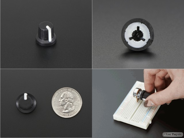
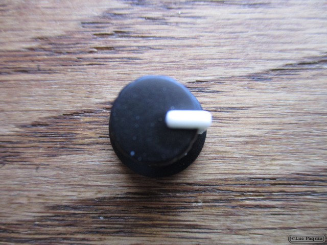
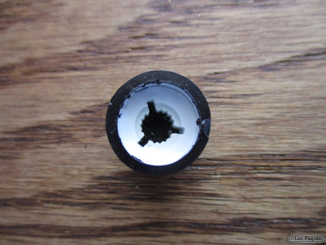
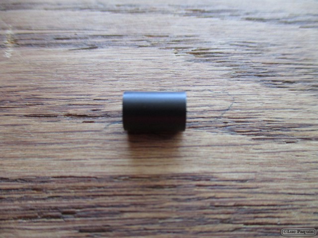
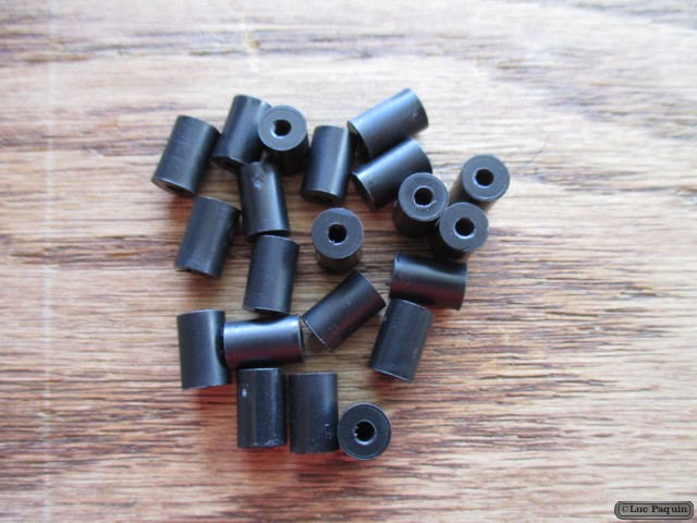
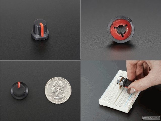
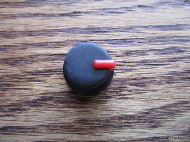
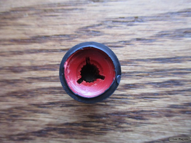
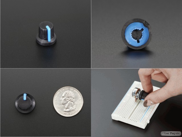
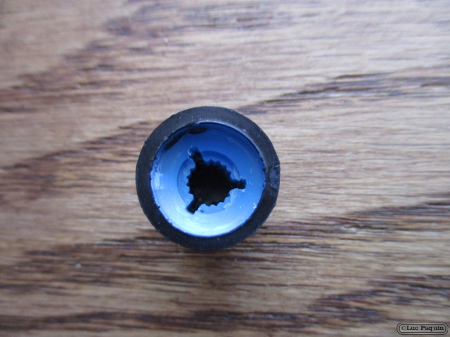
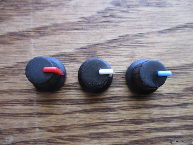
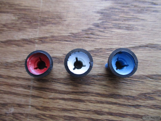
Sorry – we thought that was clever. And while it wasn’t really, this potentiometer knob definitely is. It’s a ‘soft touch’ T18 knob that works great with our Panel Mount 10K, Panel Mount 1K, and Panel Mount 100K potentiometers. The knob is designed to set directly on the potentiometer’s ridges so it’s an easy & secure fit. It has a nice feel, with a rubbery grip, tweaking it is quite fulfilling.
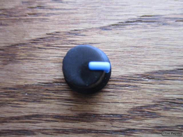
This is the blue version and it has a nice deep color on the inside with a striking blue line on the outside for great visibility with whatever you’re making. We also carry it in white and red if you’re looking for a variety of colors.
Technical Details
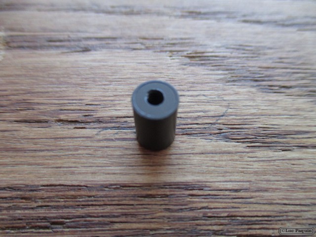
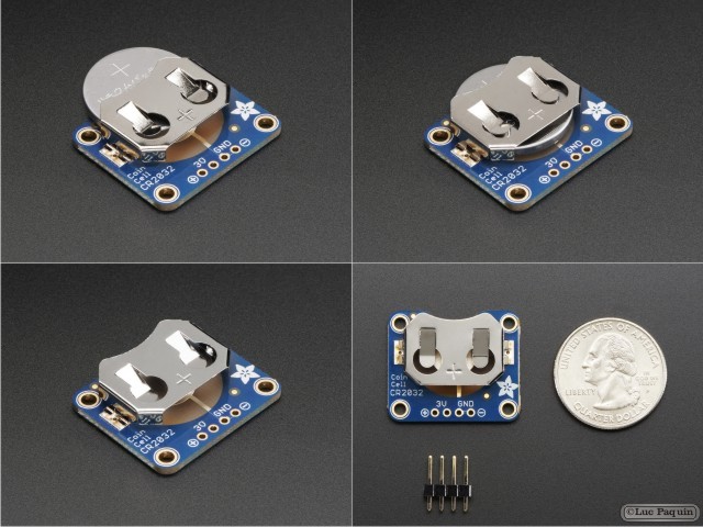
- Diameter of the top: 11mm / 0.4″
- Diameter of the base: 15mm / 0.6″
- Weight: 1g
- Colour: Blue
Don Luc