
——
#DonLucElectronics #DonLuc #Sound #Metronome #Project #Fritzing #Programming #Electronics #Microcontrollers #Consultant
——
——
——
——
Metronome
A metronome is a device that produces an audible click or other sound at a regular interval that can be set by the user, typically in Beats Per Minute (BPM). Metronomes may include synchronized visual motion. Musicians use the device to practise playing to a regular pulse. In the 20th century, electronic metronomes and software metronomes were invented.
Musicians practise with metronomes to improve their timing, especially the ability to stick to a regular tempo. Metronome practice helps internalize a clear sense of timing and tempo. Composers and conductors often use a metronome as a standard tempo reference, and may play, sing, or conduct to the metronome. The metronome is used by composers to derive beats per minute if they want to indicate that in a composition. Conductors use a metronome to note their preferred tempo in each section.
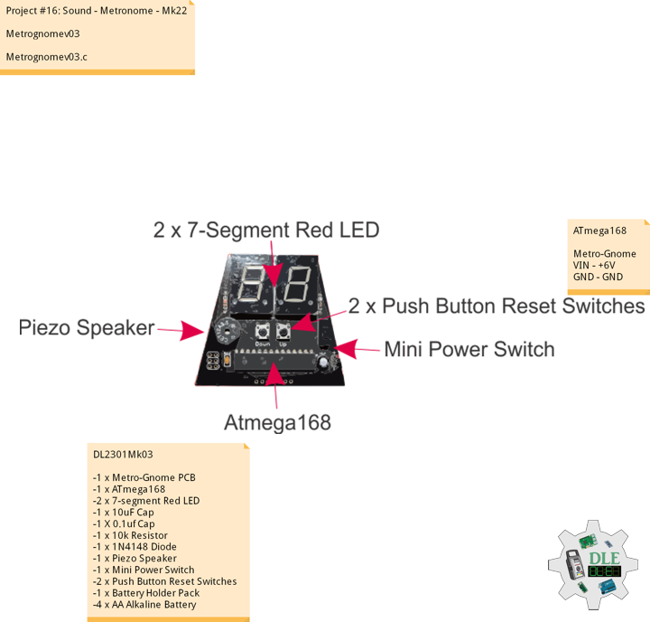
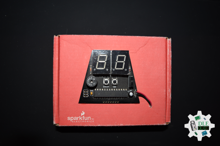
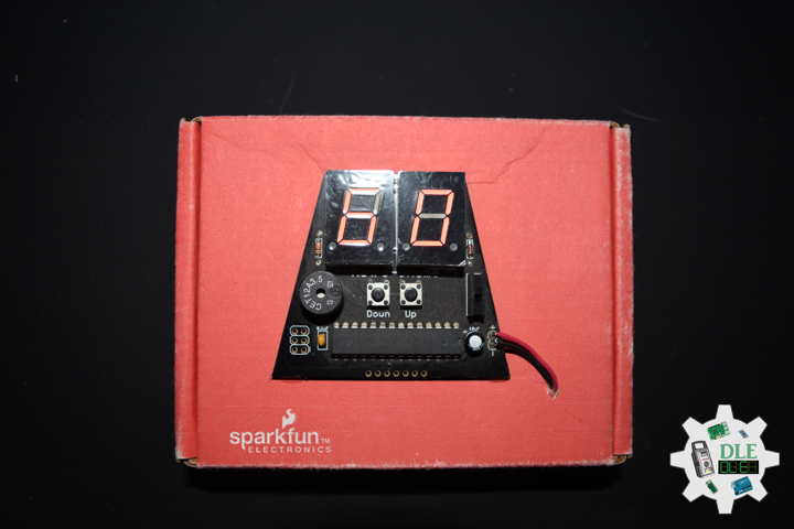
SparkFun Metro-Gnome
The SparkFun Metro-Gnome is a basic digital metronome used to keep time during music practice. This is a basic kit that goes together in 15-20 minutes for people learning to solder, and 5-10 minutes for those with a bit of experience.
DL2301Mk03
-1 x Metro-Gnome PCB
-1 x ATmega168
-2 x 7-Segment Red LED
-1 x 10uF Capacitor
-1 X 0.1uf Capacitor
-1 x 10k Resistor
-1 x 1N4148 Diode
-1 x Piezo Speaker
-1 x Mini Power Switch
-2 x Push Button Reset Switches
-1 x Battery Holder Pack
-4 x AA Alkaline Battery
ATmega168
Metro-Gnome
VIN – +6V
GND – GND
——
Metrognomev03
Metrognomev03.c
// Metronome-v03

#define F_CPU 1024000	// Adjust this to get the clock more precise

#include <avr/io.h>
#include <util/delay.h>
#include <avr/interrupt.h>

#define BUZZER1 	1
#define BUZZER1_PORT	PORTB
#define BUZZER2		2
#define BUZZER2_PORT	PORTB

#define sbi(port_name, pin_number)   (port_name |= 1<<pin_number)
#define cbi(port_name, pin_number)   ((port_name) &= (uint8_t)~(1 << pin_number))

uint16_t countUp = F_CPU/1024;		// Dividing clock by 1024
uint16_t speed = 60;		// Program initially runs at 60 BPM
uint8_t leftDisplay = 6;		// Initialize output to show 60 BPM
uint8_t rightDisplay = 0;

void ioinit();
void display(int digit, int number);

// Interrupt Timer 1 makes the buzzer tick at proper intervals
ISR(TIMER1_COMPA_vect)
{
	int buzzPeriod = 100;
	uint32_t buzzLength = 1000;

	while(1)
    {
		//Subtract the buzzPeriod from the overall length
		if(buzzPeriod > buzzLength) break;
		buzzLength -= buzzPeriod;

		if(buzzPeriod > buzzLength) break;
		buzzLength -= buzzPeriod;

		//Toggle the buzzer at various speeds
		PINB = 0b00000010;
		_delay_us(buzzPeriod);

		PINB = 0b00000100;
		_delay_us(buzzPeriod);
    }
}

// Interrupt Timer 2 checks for button presses
ISR(TIMER0_COMPA_vect)
{
	// Check down button
    if( (PINB & (1<<4)) == 0)
	{
		if (speed == 1)		// If speed = 1 go up to 299
		{
			speed = 299;
			rightDisplay = 9;
			leftDisplay = 9;
		}
		else if ((rightDisplay == 0) && (leftDisplay == 0))
		{
			rightDisplay = 9;
			leftDisplay = 9;
			speed--;
		}
		else if (rightDisplay == 0)
		{
			rightDisplay = 9;
			leftDisplay--;
			speed--;
		}
		else
		{
			rightDisplay--;
			speed--;
		}
		// Reset counter and adjust compare register
		TCNT1 = 0x00;
		OCR1A = (countUp*60)/speed;
	}
	// Check up button
	if((PINB & (1<<5)) == 0)
	{
		if (speed == 299)
		{
			speed = 1;
			rightDisplay = 1;
			leftDisplay = 0;
		}
		else if ((rightDisplay == 9) && (leftDisplay == 9))
		{
			rightDisplay = 0;
			leftDisplay = 0;
			speed++;
		}
		else if (rightDisplay == 9)
		{
			rightDisplay = 0;
			leftDisplay++;
			speed++;
		}
		else
		{
			rightDisplay++;
			speed++;
		}
		// Reset counter and adjust compare register
		TCNT1 = 0x00;
		OCR1A = (countUp*60)/speed;
	}
}

int main()
{
	int flag = 0;

	ioinit();

	while(1)	// Main loop PWM's the two displays at 1kHz
	{
		if (flag == 0)
		{
			cbi(PORTC, 1);	// Turn right display off
			display(0, leftDisplay);	// Output to left display
			flag = 1;
		}
		else
		{
			cbi(PORTC, 0);	// Turn left display off
			display(1, rightDisplay);	// Output to right display
			flag = 0;
		}
		_delay_us(10);
		PORTD = 0xFF;
		cbi(PORTC, 0);
		cbi(PORTC, 1);
		_delay_us(30);
	}

	return 0;
}

void ioinit()
{
	// set PORTB for Buzzer and buttons
	DDRB = DDRB | 0b00110110;
	PORTB = PORTB | 0b00110000;
	// set PORTC for DIGI select
	DDRC = 0b0000011;
	PINC = 0b0000011;
	// set PORTD for display
	DDRD = 0b11111111;

	// Set 16-bit Timer 1 for clicking
	TCCR1A = 0x00;
	TCCR1B = (_BV(WGM12) | _BV(CS12) | _BV(CS10));	// Divide clock by 1024, CTC mode
	OCR1A = (countUp*60)/speed;	// Set top of counter
	TIMSK1 = _BV(OCIE1A);	// Enable OCR1A interrupt

	// Set Timer 0 to check button press
	TCCR0A = _BV(WGM01);
	TCCR0B = _BV(CS00) | _BV(CS02);
	OCR0A = 100;		// OCCR0A can be adjusted to change the button debounce time
	TIMSK0 = _BV(OCIE0A);

	sei();	// Enable interrupts
}

// This will output the corresponding
// 'number' to digit 0 (left) or 1 (right)
void display(int digit, int number)
{
	//cbi(PORTC, digit);	// Ties display to ground

	if (digit == 0)
		sbi(PORTC, 0);	// Ties display to ground
	else if (digit == 1)
		sbi(PORTC, 1);

	switch(number)	// Set PIND, display pins, to correct output
	{
		case 0:
			PORTD = 0b11000000;
			break;
		case 1:
			PORTD = 0b11111001;
			break;
		case 2:
			PORTD = 0b10100100;
			break;
		case 3:
			PORTD = 0b10110000;
			break;
		case 4:
			PORTD = 0b10011001;
			break;
		case 5:
			PORTD = 0b10010010;
			break;
		case 6:
			PORTD = 0b10000010;
			break;
		case 7:
			PORTD = 0b11111000;
			break;
		case 8:
			PORTD = 0b10000000;
			break;
		case 9:
			PORTD = 0b10010000;
			break;
	}
	// Turn decimal point on if above 100 & 200
	if ((digit == 0) && (speed >= 200))
		cbi(PORTD, 7);
	if ((digit == 1) && (speed >= 100))
		cbi(PORTD, 7);
}
——
People can contact us: https://www.donluc.com/?page_id=1927
Technology Experience
- Programming Language
- Single-Board Microcontrollers (PIC, Arduino, Raspberry Pi,Espressif, etc…)
- IoT
- Wireless (Radio Frequency, Bluetooth, WiFi, Etc…)
- Robotics
- Camera and Video Capture Receiver Stationary, Wheel/Tank and Underwater Vehicle
- Unmanned Vehicles Terrestrial and Marine
- Machine Learning
- RTOS
- Research & Development (R & D)
Instructor, E-Mentor, STEAM, and Arts-Based Training
- Programming Language
- IoT
- PIC Microcontrollers
- Arduino
- Raspberry Pi
- Espressif
- Robotics
Follow Us
Luc Paquin – Curriculum Vitae – 2023
https://www.donluc.com/luc/
Web: https://www.donluc.com/
Facebook: https://www.facebook.com/neosteam.labs.9/
YouTube: https://www.youtube.com/@thesass2063
Twitter: https://twitter.com/labs_steam
Pinterest: https://www.pinterest.com/NeoSteamLabs/
Instagram: https://www.instagram.com/neosteamlabs/
Don Luc