DonLuc
Consultant
A consultant is a professional who provides expert advice in a particular area such as security (electronic or physical), management, education, accountancy, law, human resources, marketing (and public relations), finance, engineering, science or any of many other specialized fields.
A consultant is usually an expert or an experienced professional in a specific field and has a wide knowledge of the subject matter. The role of consultant outside the medical sphere (where the term is used specifically for a grade of doctor) can fall under one of two general categories:
Internal consultant: someone who operates within an organization but is available to be consulted on areas of their specialization by other departments or individuals (acting as clients); or
External consultant: someone who is employed externally to the client (either by a consulting firm or some other agency) whose expertise is provided on a temporary basis, usually for a fee. Consulting firms range in size from sole proprietorships consisting of a single consultant, small businesses consisting of a small number of consultants, to mid- to large consulting firms, which in some cases are multinational corporations. This type of consultant generally engages with multiple and changing clients, which are typically companies, non-profit organizations, or governments.
By hiring a consultant, clients have access to deeper levels of expertise than would be financially feasible for them to retain in-house on a long-term basis. Moreover, clients can control their expenditures on consulting services by only purchasing as much services from the outside consultant as desired.
Consultants provide their advice to their clients in a variety of forms. Reports and presentations are often used. However, in some specialized fields, the consultant may develop customized software or other products for the client. Depending on the nature of the consulting services and the wishes of the client, the advice from the consultant may be made public, by placing the report or presentation online, or the advice may be kept confidential, and only given to the senior executives of the organization paying for the consulting services.
Why be a consultant?
There are many reasons why one would want to become a consultant.
Some would love to ditch their corporate jobs and be lured to become self-employed. After being self-employed all of my adult life I would not know what to recommend to those as I do not know any other way. I know that my wife Norma had problems getting adapted to the consultant way, as she had the opposite experience of being employed all of her adult life by banks or investment firm. Being self-employed to her was very traumatic at first, and still is when business slows down.
Leaving the security of a good job is very hard to do, especially if you are used to have and count on a regular income. It becomes very difficult to plan things like mortgages and car loans or other regular types of expenses, when you are never sure of exactly of what your income will be next month. For some this is something they cannot live with, and to others like me, it is something so normal that you never really think about it. You just have to be very careful with your expenses and plan your life and budget accordingly. Those who cannot live with that kind of uncertainty should no even think of being a consultant or to be self-employed for that matter.
Other people would love to work at home like a lot of us do. For that too you need to have a certain sense of organization to be able to do it without all the normal distractions around the house preventing you from doing any works. It all depends on how well organized you are and how you can isolate yourself from other things and concentrate on your work. Most people find it difficult at first, but get used to it with time. For those who can’t it might be better to think about working for some consulting firm that will place you at their client’s site.
Others are lured by the large fees that some consultants charge. This might look very tempting at first glance, but when you start analyzing it in depth once you take this high fee, deduct from it your operating expenses, the equipment, tools and software you might need to perform your consulting, publicity, legal and accounting fees, office expenses, and the fact that you are rarely billing the full time you are working each week, you might not be making a huge amount more than you are doing right now at your current job. Add to that all of those other things that you never think of, like the fact that normally when you are on your own you do not have the niceties of things like health and other types of insurance, retirement plans, benefits and more.
Does that mean that you should not become a consultant? Of course not! If you can live with all of the above and more and have the personality to enjoy those kinds of challenges and live your life differently than most of your neighbors and friends, consulting is an immensely rewarding profession that can offer you things that you would never have the chance of experiencing otherwise. I would not even dream of doing something else and if I have not become a consultant so long ago I would never had the life and the experiences I have had. Sure, it can be very hard at times, all the good things in life are hard to achieve, but the rewards are huge for those who like a challenge and can focus to achieve their goals.
What type of consultant am I?
There are many ways of defining oneself as a consultant. The traditional consultant is normally somebody who is an expert in his field with either a long career behind him or very specific specialized knowledge that is not common in a field. He is hired to resolve specific issues by clients or “consulted” when his client need information on some topic that they are an expert.
The term is also used for people who do contract work in a specific field. They usually work one contract at a time and they will build something, or deliver a project for their client. This used to be called a contractor, but these days the definition is getting fuzzier as a lot of “Consulting” firms are normally placing “Contractors” at their client’s sites and calling them “Consultants”.
More and more self-employed workers, or workers moonlighting in their spare times are now calling themselves “Consultants” though they might not be doing much actual consulting or contracting work.
This confuses a lot of people looking to hire external resources as a lot of people are calling themselves “Consultants” and actually offer a wide variety of services only some of which are actual consulting. It is a good thing for people who which to hire external help, consultant or other, to make sure before they start looking that they know what kind of help they are looking for.
Coming back to the main topic of this post. I started in the mid 1980’s as a traditional consultant in the food and wine business. My various clients hired me for my specialized knowledge and consulted me on various topics and I would also do specific contracts for them on a regular basis like travel to various places worldwide to purchase various things for them or just analyze what was available in the market. I started during that period doing consulting work in computer graphics and animation which was a new field in those days and then I started to consult more and more about IT using the knowledge I had as I trained as a mainframe programmer at university ten years earlier.
In the early 1990’s I was doing more and more IT consulting for local clients and prior to the advent of the Internet, in the old days of the original CompuServe network of which I had been a member since around 1986, I started consulting with many clients worldwide from my office at the edge of a lake in Northern Quebec. I also started doing more and more contracting for various large companies in the United States and elsewhere. I spent most of the 1990’s traveling over 6 months of the year to work onsite with many clients worldwide. The rest of the year was spent either consulting or contracting, as I do differentiate, for my clients from my office in Quebec.
In the late 1990’s during the time of the big Internet crash, I started developing my own line of software products for retail business management, point of sales, ticketing systems, kiosk systems, and decision support systems. In 2003 I moved to Mexico City to promote some of my products and to get away from the cold of Quebec as my Mexican wife was feeling somewhat unaccustomed to the long winters and isolated over there.
Today I am back to being a traditional consultant full time, though I still work regularly on my software products and actively promote and find new markets for them. I continue my IT consulting as always and consult with businesses looking for new markets or with startups looking for advice. I also do contract work developing innovative software, integrate software with hardware, and of course I still do consult in the food and wine industry, my first love.
My motto has always been since I was a kid that I need to learn something new every single day as if I do not that day is wasted. Since I have been in the consulting business for so long, and tried hard to not waste any day of it, I have accumulated a lot of knowledge over the years. This is why for many years now that I love to teach and give conferences to pass this knowledge to others. I tend to be very passionate about this, as I have always love to educate people and convince them that they should learn something new every day. My wife Norma always says that I should have been a preacher, but what I am really is a traditional consultant that likes to share is experience and knowledge with others.
Common Types Don Luc
Information-Technology (IT) Consultants in many disciplines such as computer hardware, software engineering, or networks.
Process Consultants who are specialists in the design or improvement of operational processes and can be specific to the industry or sector.
3D Consultants who are specialists in the field of 3D scanning, printing, modeling, designing, engineering, building, and everything that has to do with the three dimensions.
Internet Consultants who are specialists in business use of the internet and keep themselves up-to-date with new and changed capabilities offered by the web. Ideally internet consultants also have practical experience and expertise in management skills such as strategic planning, change, projects, processes, training, team-working and customer satisfaction.
Specialties Don Luc:
IT and Technology Consulting
IT Project Feasibility Studies
IT Project Management
3D Consultants
Custom Software Programming (Desktop, Web and Mobile)
Microcontroller programming
Software Internationalization and Localization
Hardware-Software Integration Consulting
Factory and Process Automation Consulting
Robotics Consulting
Custom Electronic Hardware Design and Sourcing
R&D Services
Don Luc
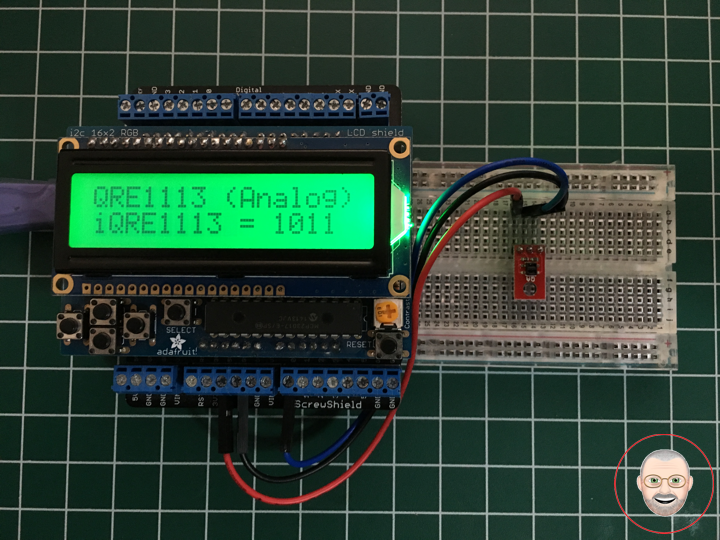
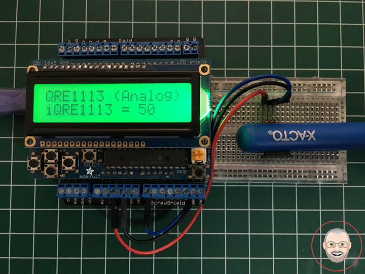
Project #7: RGB LCD Shield – Line Sensor Breakout – Mk07
Line Sensor Breakout – QRE1113 (Analog)
Description
This version of the QRE1113 breakout board features an easy-to-use analog output, which will vary depending on the amount of IR light reflected back to the sensor. This tiny board is perfect for line sensing applications and can be used in both 3.3V and 5V systems.
The board’s QRE1113 IR reflectance sensor is comprised of two parts – an IR emitting LED and an IR sensitive phototransistor. When you apply power to the VCC and GND pins the IR LED inside the sensor will illuminate. A 100 Ohm resistor is on-board and placed in series with the LED to limit current. A 10k Ohm resistor pulls the output pin high, but when the light from the LED is reflected back onto the phototransistor the output will begin to go lower. The more IR light sensed by the phototransistor, the lower the output voltage of the breakout board.
These sensors are widely used in line following robots – white surfaces reflect much more light than black, so, when directed towards a white surface, the voltage output will be lower than that on a black surface.
The power input and analog output pins are brought out to a 3-pin, 0.1″ pitch header. The board also has a single mounting hole if you want to screw the board onto something.
Features
* 5VDC operating voltage
* 25mA supply current
* Optimal sensing distance: 0.125″ (3mm)
* 0.30 x 0.55 “ (7.62 x 13.97 mm)
Common Reflectance Sensor
The QRE1113 is a common reflectance sensor often used in robotic line followers. The sensor works by shining an IR LED down and seeing how much of that light bounces back using a phototransistor. Because dark colors will bounce back less of the light, the sensor can be used to tell the difference between white and black areas. So an array of these can be used to help a robot determine where a dark line is on the ground so it can follow it. But they can also be used to determine proximity under an inch.
The an analog input on your microcontroller but still need an analog reading of how much light was reflected. It does this by allowing you to charge a capacitor on the board, and then timing how long it takes to discharge. The more light that is reflected, the less time it takes to discharge the capacitor. Hooking the QRE1113 to your Arduino is very simple. It just needs power (5V), ground, and an analog pin.
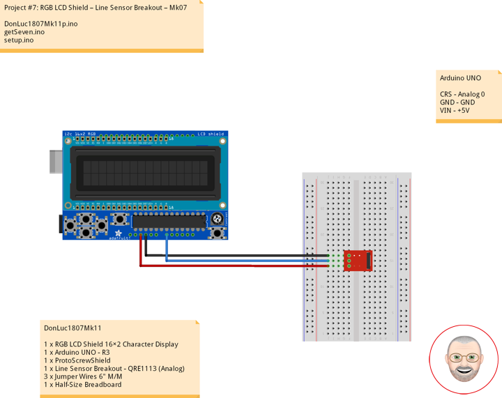
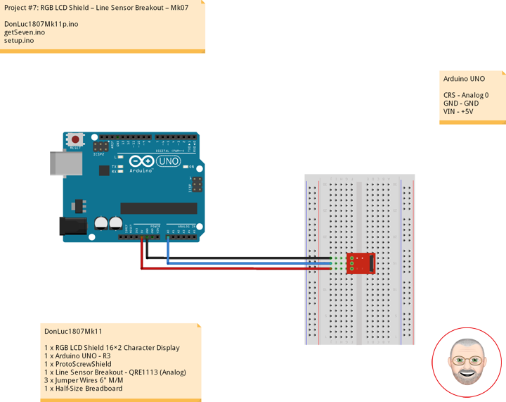
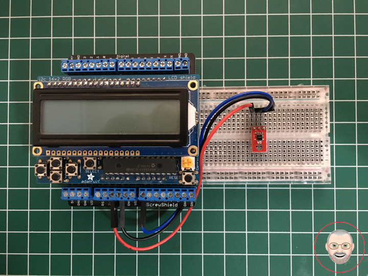
DonLuc1807Mk11
1 x RGB LCD Shield 16×2 Character Display
1 x Arduino UNO – R3
1 x ProtoScrewShield
1 x Line Sensor Breakout – QRE1113 (Analog)
3 x Jumper Wires 6″ M/M
1 x Half-Size Breadboard
Arduino UNO
CRS – Analog 0
GND – GND
VIN – +5V
DonLuc1807Mk11p.ino
// ***** Don Luc *****
// Software Version Information
// Project #7: RGB LCD Shield – Line Sensor Breakout – Mk07
// 7-11
// DonLuc1807Mk10p 7-11
// RGB LCD Shield
// QRE1113 (Analog)

// include the library code:
#include <Adafruit_MCP23017.h>
#include <Adafruit_RGBLCDShield.h>

Adafruit_RGBLCDShield RGBLCDShield = Adafruit_RGBLCDShield();
#define GREEN 0x2

// Seven-Segment Display
int iQRE1113 = A0;       // iQRE1113
int iQRE1113Value = 0;   // iQRE1113Value

void loop()
{

  // QRE1113 (Analog)
  isCRS();

  delay(2000);

  // Clear
  RGBLCDShield.clear();

}
getSeven.ino
// Line Sensor Breakout - QRE1113
void isCRS()
{

  // Display
  // Set the cursor to column 0, line 0
  RGBLCDShield.setCursor(0,0);
  RGBLCDShield.print("QRE1113 (Analog)");       // Line Sensor Breakout - QRE1113

  iQRE1113Value = analogRead(iQRE1113);

  // Set the cursor to column 0, line 1
  RGBLCDShield.setCursor(0, 1);
  RGBLCDShield.print("iQRE1113 = ");            // iQRE1113
  RGBLCDShield.print( iQRE1113Value );          // iQRE1113Value

}
setup.ino
// Setup
void setup()
{

  // set up the LCD's number of columns and rows:
  RGBLCDShield.begin(16, 2);
  RGBLCDShield.setBacklight(GREEN);

  // Display
  // Set the cursor to column 0, line 0
  RGBLCDShield.setCursor(0,0);
  RGBLCDShield.print("Don Luc");           // Don luc
  // Set the cursor to column 0, line 1
  RGBLCDShield.setCursor(0, 1);
  RGBLCDShield.print("QRE1113 (Analog)");  // Seven-Segment Display
  delay(5000);

  // Clear
  RGBLCDShield.clear();

}
Don Luc
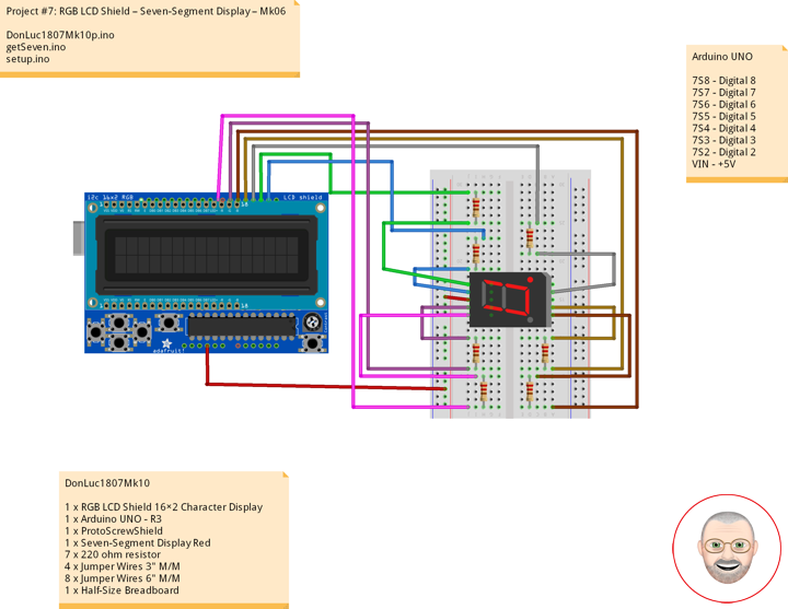
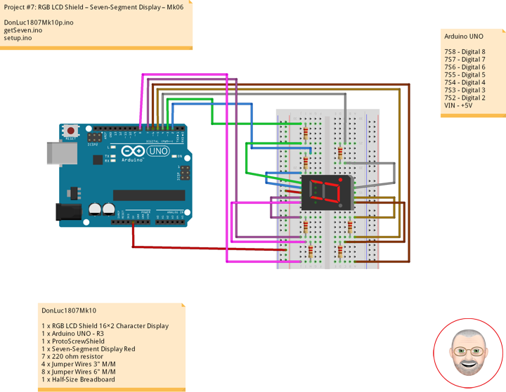
Project #7: RGB LCD Shield – Seven-Segment Display – Mk06
Seven-Segment Display
A seven-segment display (SSD), or seven-segment indicator, is a form of electronic display device for displaying decimal numerals that is an alternative to the more complex dot matrix displays.
Seven-segment displays are widely used in digital clocks, electronic meters, basic calculators, and other electronic devices that display numerical information.
Your basic 7-segment LED. Common anode. Two decimal points, but only the one on the right is wired. Digit height is 0.6″. Overall height is 1″.
Common Cathode
In a common-cathode display, the positive terminal of all the eight LEDs are connected together and then connected to iSeven2 and iSeven8. To turn on an individual segment, you ground one of the pins. The following diagram shows the internal structure of the common-cathode seven-segment display.
The internal structure of both types is nearly the same. The difference is the polarity of the LEDs and common terminal. In a common cathode seven-segment display, all seven LEDs plus a dot LED have the cathodes connected To use this display, we need to connect VIN to make the individual segments light up. The following diagram shows the internal structure of common-cathode seven-segment display.
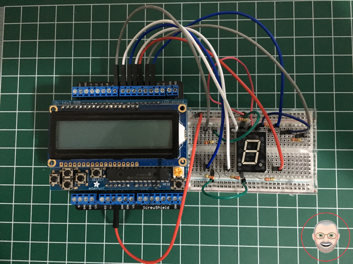
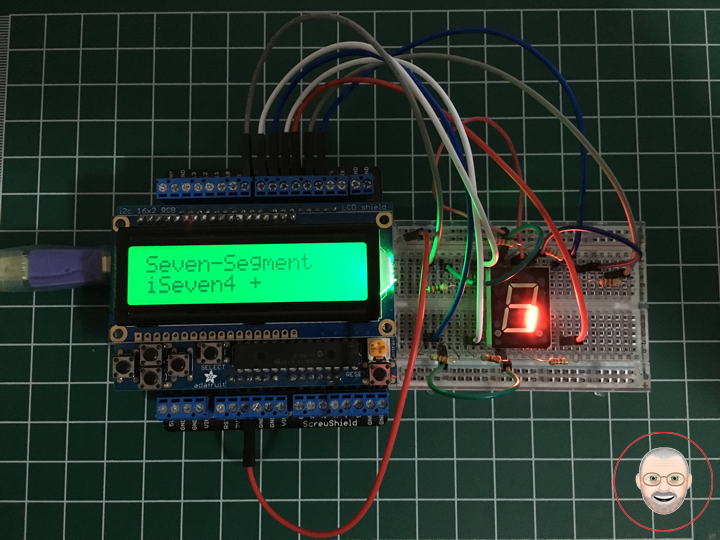
If your Arduino application only needs to display numbers, consider using a seven-segment display. The severn-segment display has seven LEDs arranged in the shape of number eight. They are easy to use and cost effective. The picture below shows a typical seven-segment display.
DonLuc1807Mk10
1 x RGB LCD Shield 16×2 Character Display
1 x Arduino UNO – R3
1 x ProtoScrewShield
1 x Seven-Segment Display Red
7 x 220 ohm resistor
4 x Jumper Wires 3″ M/M
8 x Jumper Wires 6″ M/M
1 x Half-Size Breadboard
Arduino UNO
7S8 – Digital 8
7S7 – Digital 7
7S6 – Digital 6
7S5 – Digital 5
7S4 – Digital 4
7S3 – Digital 3
7S2 – Digital 2
VIN – +5V
DonLuc1807Mk10p.ino
// ***** Don Luc *****
// Software Version Information
// Project #7: RGB LCD Shield – Seven-Segment Display – Mk06
// 7-10
// DonLuc1807Mk10p 7-10
// RGB LCD Shield
// Seven-Segment Display

// include the library code:
#include <Adafruit_MCP23017.h>
#include <Adafruit_RGBLCDShield.h>

Adafruit_RGBLCDShield RGBLCDShield = Adafruit_RGBLCDShield();
#define GREEN 0x2

// Seven-Segment Display
int iSeven2 = 2;     // iSeven2
int iSeven3 = 3;     // iSeven3
int iSeven4 = 4;     // iSeven4
int iSeven5 = 5;     // iSeven5
int iSeven6 = 6;     // iSeven6
int iSeven7 = 7;     // iSeven7
int iSeven8 = 8;     // iSeven8

void loop()
{

  // Seven-Segment Display
  isSeven();

  // Clear
  RGBLCDShield.clear();

}
getSeven.ino
// Seven-Segment Display
void isSeven()
{

  // Display
  // Set the cursor to column 0, line 0
  RGBLCDShield.setCursor(0,0);
  RGBLCDShield.print("Seven-Segment");          // Seven-Segment Display

  // Set the cursor to column 0, line 1
  RGBLCDShield.setCursor(0, 1);
  RGBLCDShield.print("iSeven2 +    ");          // iSeven2 +
  digitalWrite(iSeven2, LOW);

  delay(5000);

  // Seven - Off
  isSevOff();

  // Set the cursor to column 0, line 1
  RGBLCDShield.setCursor(0, 1);
  RGBLCDShield.print("iSeven2 -      ");        // iSeven2 -

  delay(2000);

  // Set the cursor to column 0, line 1
  RGBLCDShield.setCursor(0, 1);
  RGBLCDShield.print("iSeven3 +    ");          // iSeven3 +
  digitalWrite(iSeven3, LOW);

  delay(5000);

  // Seven - Off
  isSevOff();

  // Set the cursor to column 0, line 1
  RGBLCDShield.setCursor(0, 1);
  RGBLCDShield.print("iSeven3 -      ");        // iSeven3 -

  delay(2000);

  // Set the cursor to column 0, line 1
  RGBLCDShield.setCursor(0, 1);
  RGBLCDShield.print("iSeven4 +   ");           // iSeven4 +
  digitalWrite(iSeven4, LOW);

  delay(5000);

  // Seven - Off
  isSevOff();

  // Set the cursor to column 0, line 1
  RGBLCDShield.setCursor(0, 1);
  RGBLCDShield.print("iSeven4 -      ");        // iSeven4 -

  delay(2000);

  // Set the cursor to column 0, line 1
  RGBLCDShield.setCursor(0, 1);
  RGBLCDShield.print("iSeven5 +   ");           // iSeven5 +
  digitalWrite(iSeven5, LOW);

  delay(5000);

  // Seven - Off
  isSevOff();

  // Set the cursor to column 0, line 1
  RGBLCDShield.setCursor(0, 1);
  RGBLCDShield.print("iSeven5 -      ");        // iSeven5 -

  delay(2000);

  // Set the cursor to column 0, line 1
  RGBLCDShield.setCursor(0, 1);
  RGBLCDShield.print("iSeven6 +   ");           // iSeven6 +
  digitalWrite(iSeven6, LOW);

  delay(5000);

  // Seven - Off
  isSevOff();

  // Set the cursor to column 0, line 1
  RGBLCDShield.setCursor(0, 1);
  RGBLCDShield.print("iSeven6 -      ");        // iSeven6 -

  delay(2000);

  // Set the cursor to column 0, line 1
  RGBLCDShield.setCursor(0, 1);
  RGBLCDShield.print("iSeven7 +   ");           // iSeven7 +
  digitalWrite(iSeven7, LOW);

  delay(5000);

  // Seven - Off
  isSevOff();

  // Set the cursor to column 0, line 1
  RGBLCDShield.setCursor(0, 1);
  RGBLCDShield.print("iSeven7 -      ");        // iSeven7 -

  delay(2000);

  // Set the cursor to column 0, line 1
  RGBLCDShield.setCursor(0, 1);
  RGBLCDShield.print("iSeven8 +   ");           // iSeven8 +
  digitalWrite(iSeven8, LOW);

  delay(5000);

  // Seven - Off
  isSevOff();

  // Set the cursor to column 0, line 1
  RGBLCDShield.setCursor(0, 1);
  RGBLCDShield.print("iSeven8 -      ");        // iSeven8 -

  delay(2000);

  // Set the cursor to column 0, line 1
  RGBLCDShield.setCursor(0, 1);
  RGBLCDShield.print("iSeven 0    ");           // iSeven 0
  digitalWrite(iSeven2, LOW);
  digitalWrite(iSeven3, LOW);
  digitalWrite(iSeven4, LOW);
  digitalWrite(iSeven5, LOW);
  digitalWrite(iSeven6, LOW);
  digitalWrite(iSeven7, LOW);

  delay(5000);

  // Seven - Off
  isSevOff();

  // Set the cursor to column 0, line 1
  RGBLCDShield.setCursor(0, 1);
  RGBLCDShield.print("Seven - Off    ");        // Seven - Off

  delay(2000);

  // Set the cursor to column 0, line 1
  RGBLCDShield.setCursor(0, 1);
  RGBLCDShield.print("iSeven 1    ");           // iSeven 1
  digitalWrite(iSeven3, LOW);
  digitalWrite(iSeven4, LOW);

  delay(5000);

  // Seven - Off
  isSevOff();

  // Set the cursor to column 0, line 1
  RGBLCDShield.setCursor(0, 1);
  RGBLCDShield.print("Seven - Off    ");        // Seven - Off

  delay(2000);

  // Set the cursor to column 0, line 1
  RGBLCDShield.setCursor(0, 1);
  RGBLCDShield.print("iSeven 2    ");           // iSeven 2
  digitalWrite(iSeven2, LOW);
  digitalWrite(iSeven3, LOW);
  digitalWrite(iSeven5, LOW);
  digitalWrite(iSeven6, LOW);
  digitalWrite(iSeven8, LOW);

  delay(5000);

  // Seven - Off
  isSevOff();

  // Set the cursor to column 0, line 1
  RGBLCDShield.setCursor(0, 1);
  RGBLCDShield.print("Seven - Off    ");        // Seven - Off

  delay(2000);

  // Set the cursor to column 0, line 1
  RGBLCDShield.setCursor(0, 1);
  RGBLCDShield.print("iSeven 3    ");           // iSeven 3
  digitalWrite(iSeven2, LOW);
  digitalWrite(iSeven3, LOW);
  digitalWrite(iSeven4, LOW);
  digitalWrite(iSeven5, LOW);
  digitalWrite(iSeven8, LOW);

  delay(5000);

  // Seven - Off
  isSevOff();

  // Set the cursor to column 0, line 1
  RGBLCDShield.setCursor(0, 1);
  RGBLCDShield.print("Seven - Off    ");        // Seven - Off

  delay(2000);

  // Set the cursor to column 0, line 1
  RGBLCDShield.setCursor(0, 1);
  RGBLCDShield.print("iSeven 4    ");           // iSeven 4
  digitalWrite(iSeven3, LOW);
  digitalWrite(iSeven4, LOW);
  digitalWrite(iSeven7, LOW);
  digitalWrite(iSeven8, LOW);

  delay(5000);

  // Seven - Off
  isSevOff();

  // Set the cursor to column 0, line 1
  RGBLCDShield.setCursor(0, 1);
  RGBLCDShield.print("Seven - Off    ");        // Seven - Off

  delay(2000);

  // Set the cursor to column 0, line 1
  RGBLCDShield.setCursor(0, 1);
  RGBLCDShield.print("iSeven 5    ");           // iSeven 5
  digitalWrite(iSeven2, LOW);
  digitalWrite(iSeven4, LOW);
  digitalWrite(iSeven5, LOW);
  digitalWrite(iSeven7, LOW);
  digitalWrite(iSeven8, LOW);

  delay(5000);

  // Seven - Off
  isSevOff();

  // Set the cursor to column 0, line 1
  RGBLCDShield.setCursor(0, 1);
  RGBLCDShield.print("Seven - Off    ");        // Seven - Off

  delay(2000);

  // Set the cursor to column 0, line 1
  RGBLCDShield.setCursor(0, 1);
  RGBLCDShield.print("iSeven 6    ");           // iSeven 6
  digitalWrite(iSeven2, LOW);
  digitalWrite(iSeven4, LOW);
  digitalWrite(iSeven5, LOW);
  digitalWrite(iSeven6, LOW);
  digitalWrite(iSeven7, LOW);
  digitalWrite(iSeven8, LOW);

  delay(5000);

  // Seven - Off
  isSevOff();

  // Set the cursor to column 0, line 1
  RGBLCDShield.setCursor(0, 1);
  RGBLCDShield.print("Seven - Off    ");        // Seven - Off

  delay(2000);

  // Set the cursor to column 0, line 1
  RGBLCDShield.setCursor(0, 1);
  RGBLCDShield.print("iSeven 7    ");           // iSeven 7
  digitalWrite(iSeven2, LOW);
  digitalWrite(iSeven3, LOW);
  digitalWrite(iSeven4, LOW);

  delay(5000);

  // Seven - Off
  isSevOff();

  // Set the cursor to column 0, line 1
  RGBLCDShield.setCursor(0, 1);
  RGBLCDShield.print("Seven - Off    ");        // Seven - Off

  delay(2000);

  // Set the cursor to column 0, line 1
  RGBLCDShield.setCursor(0, 1);
  RGBLCDShield.print("iSeven 8    ");           // iSeven 8
  digitalWrite(iSeven2, LOW);
  digitalWrite(iSeven3, LOW);
  digitalWrite(iSeven4, LOW);
  digitalWrite(iSeven5, LOW);
  digitalWrite(iSeven6, LOW);
  digitalWrite(iSeven7, LOW);
  digitalWrite(iSeven8, LOW);

  delay(5000);

  // Seven - Off
  isSevOff();

  // Set the cursor to column 0, line 1
  RGBLCDShield.setCursor(0, 1);
  RGBLCDShield.print("Seven - Off    ");        // Seven - Off

  delay(2000);

  // Set the cursor to column 0, line 1
  RGBLCDShield.setCursor(0, 1);
  RGBLCDShield.print("iSeven 9    ");           // iSeven 9
  digitalWrite(iSeven2, LOW);
  digitalWrite(iSeven3, LOW);
  digitalWrite(iSeven4, LOW);
  digitalWrite(iSeven5, LOW);
  digitalWrite(iSeven7, LOW);
  digitalWrite(iSeven8, LOW);

  delay(5000);

  // Seven - Off
  isSevOff();

  // Set the cursor to column 0, line 1
  RGBLCDShield.setCursor(0, 1);
  RGBLCDShield.print("Seven - Off    ");        // Seven - Off

  delay(2000);

}

// Seven - Off
void isSevOff()
{

  // Seven - Off
  digitalWrite(iSeven2, HIGH);
  digitalWrite(iSeven3, HIGH);
  digitalWrite(iSeven4, HIGH);
  digitalWrite(iSeven5, HIGH);
  digitalWrite(iSeven6, HIGH);
  digitalWrite(iSeven7, HIGH);
  digitalWrite(iSeven8, HIGH);

}
setup.ino
// Setup
void setup()
{

  // set up the LCD's number of columns and rows:
  RGBLCDShield.begin(16, 2);
  RGBLCDShield.setBacklight(GREEN);

  // Display
  // Set the cursor to column 0, line 0
  RGBLCDShield.setCursor(0,0);
  RGBLCDShield.print("Don Luc");           // Don luc
  // Set the cursor to column 0, line 1
  RGBLCDShield.setCursor(0, 1);
  RGBLCDShield.print("Seven-Segment");     // Seven-Segment Display
  delay(5000);

  // Clear
  RGBLCDShield.clear();

  // Seven-Segment Display
  pinMode(iSeven2, OUTPUT);                // iSeven2
  pinMode(iSeven3, OUTPUT);                // iSeven3
  pinMode(iSeven4, OUTPUT);                // iSeven4
  pinMode(iSeven5, OUTPUT);                // iSeven5
  pinMode(iSeven6, OUTPUT);                // iSeven6
  pinMode(iSeven7, OUTPUT);                // iSeven7
  pinMode(iSeven8, OUTPUT);                // iSeven8

  isSevOff();                              // Seven - Off

}
Don Luc
Project #7: RGB LCD Shield – LED RGB – Mk05
LED RGB
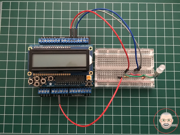
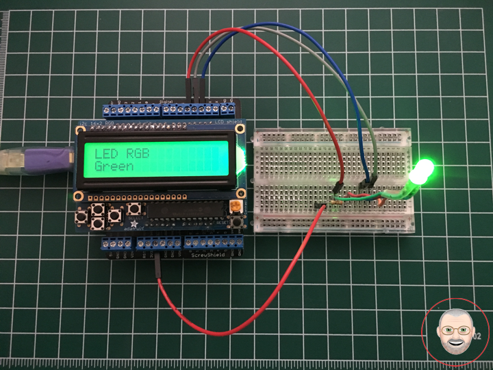
LED RGB are tri-color LEDs with red, green, and blue emitters, in general using a four-wire connection with one common lead (anode or cathode). These LEDs can have either common positive leads in the case of a common anode LED, or common negative leads in the case of a common cathode LED. Others, however, have only two leads (positive and negative) and have a built-in electronic control unit.
LED RGB (Red-Green-Blue) are actually three LEDs in one! But that doesn’t mean it can only make three colors. Because red, green, and blue are the additive primary colors, you can control the intensity of each to create every color of the rainbow. Most RGB LEDs have four pins: one for each color, and a common pin. On some, the common pin is the anode, and on others, it’s the cathode.
Circuit Schematics (Common Cathode)
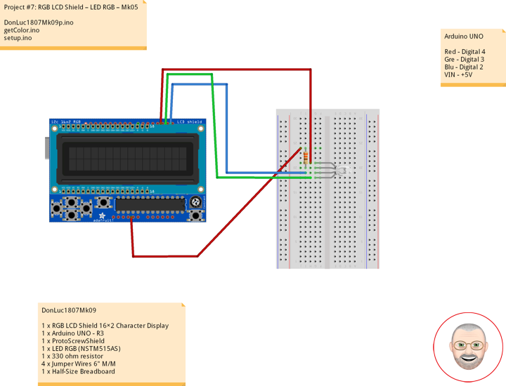
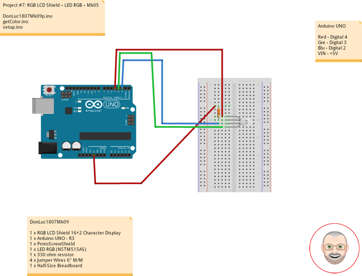
The cathode will be connected to the VIN and will be connected through 330 Ohms resistor. We will use PWM for simulating analog output which will provide different voltage levels to the LEDs so we can get the desired colors. We will use PWM for simulating analog output which will provide different voltage levels to the LEDs so we can get the desired colors.
Source Code
I will use the pins number 4, 3 and 2 and I will name them iRed, iGreen and iBlue. In the setup section we need to define them as outputs. At the bottom of the sketch we have this custom made function named setColor() which takes 3 different arguments red, green and blue. These arguments represents the brightness of the LEDs or the duty cycle of the PWM signal which is created using the analogWrite() function. These values can vary from 0 to 255 which represents 100 % duty cycle of the PWM signal or maximum LED brightness.
So now in the loop function we will make our program which will change the color of the LED each 2 second. In order to get red light on the LED we will call the setColor() function and set value of 255 for the iRed argument and 0 for the two others. Respectively we can get the two other basic colors, green and blue.
DonLuc1807Mk09
1 x RGB LCD Shield 16×2 Character Display
1 x Arduino UNO – R3
1 x ProtoScrewShield
1 x LED RGB (NSTM515AS)
1 x 330 ohm resistor
4 x Jumper Wires 6″ M/M
1 x Half-Size Breadboard
Arduino UNO
Red – Digital 4
Gre – Digital 3
Blu – Digital 2
VIN – +5V
DonLuc1807Mk09p.ino
// ***** Don Luc *****
// Software Version Information
// Project #7: RGB LCD Shield – LED RGB – Mk05
// 7-9
// DonLuc1807Mk09p 7-9
// RGB LCD Shield
// LED RGB

// include the library code:
#include <Adafruit_MCP23017.h>
#include <Adafruit_RGBLCDShield.h>

Adafruit_RGBLCDShield RGBLCDShield = Adafruit_RGBLCDShield();
#define GREEN 0x2

// LED RGB
#define COMMON_ANODE
int iBlue = 2;
int iGreen = 3;
int iRed = 4;

void loop()
{

  // LED RGB
  isColor();

  delay(500);

  // Clear
  RGBLCDShield.clear();

}
getColor.ino
// LED RGB
void isColor()
{

  // Display
  // Set the cursor to column 0, line 0
  RGBLCDShield.setCursor(0,0);
  RGBLCDShield.print("LED RGB");          // LED RGB

  // Set the cursor to column 0, line 1
  RGBLCDShield.setCursor(0, 1);
  RGBLCDShield.print("Red     ");         // Red
  setColor(255, 0, 0);                    // Red Color
  delay(2000);

  // Set the cursor to column 0, line 1
  RGBLCDShield.setCursor(0, 1);
  RGBLCDShield.print("Green   ");         // Green
  setColor(0, 255, 0);                    // Green Color

  delay(2000);

  // Set the cursor to column 0, line 1
  RGBLCDShield.setCursor(0, 1);
  RGBLCDShield.print("Blue   ");          // Blue
  setColor(0, 0, 255);                    // Blue Color
  delay(2000);

}

void setColor(int red, int green, int blue)
{

  #ifdef COMMON_ANODE
    red = 255 - red;
    green = 255 - green;
    blue = 255 - blue;
  #endif

  analogWrite(iRed, red);
  analogWrite(iGreen, green);
  analogWrite(iBlue, blue);

}
setup.ino
// Setup
void setup()
{

  // set up the LCD's number of columns and rows:
  RGBLCDShield.begin(16, 2);
  RGBLCDShield.setBacklight(GREEN);

  // Display
  // Set the cursor to column 0, line 0
  RGBLCDShield.setCursor(0,0);
  RGBLCDShield.print("Don Luc");         // Don luc
  // Set the cursor to column 0, line 1
  RGBLCDShield.setCursor(0, 1);
  RGBLCDShield.print("LED RGB");         // LED RGB

  delay(5000);

  // Clear
  RGBLCDShield.clear();

  // LED RGB
  pinMode(iBlue, OUTPUT);                 // Blue
  pinMode(iGreen, OUTPUT);                // Green
  pinMode(iRed, OUTPUT);                  // Red

}
Don Luc
Project #7: RGB LCD Shield – IR Emitters and Detectors – Mk04
Infrared Emitters and Detectors
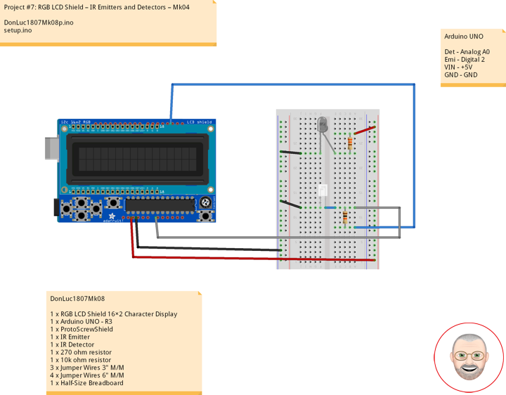
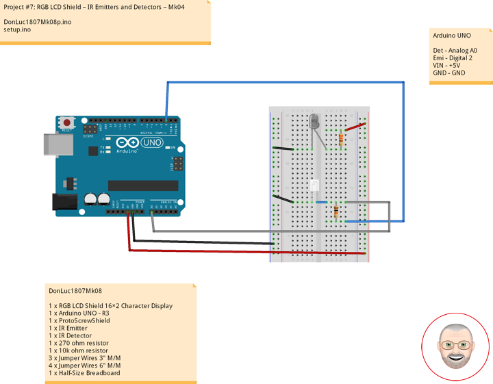
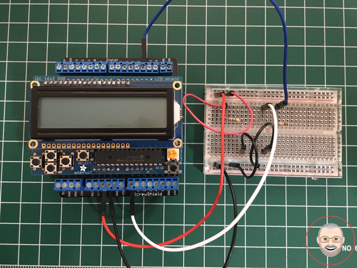
Side-looking Infrared Emitters and IR Detectors. These simple devices operate at 940nm and work well for generic IR systems including remote control and touch-less object sensing. Using a simple ADC on any microcontroller will allow variable readings to be collected from the detector. The emitter is driven up to 50mA with a current limiting resistor as with any LED device. The detect is a NPN transistor that is biased by incoming IR light.
Sold as a pair, with one Emitter and one Detector.
IR Emitter
Connect IR LED using a 270 ohm series resistor to the +5 supply (or to an Arduino pin if you want to switch the source on and off). Current draw is about 11 mA with a 270 ohm resistor. Current runs from anode to cathode. Flat on the case marks the cathode. To determine if the IR LED is the right way around.
IR Detector
A IR Detector is just like a regular transistor except the base lead is disabled or absent and light activates base current. The flat on the case marks the collector, the other lead is the emitter. Connect the collector to one end of a 10K ohm resistor and connect the other end of the resistor to a +5V supply (you can use the +5 pin on the Arduino). Connect the emitter to ground. The voltage should start out at +5V. When pointing the IR Detector, the voltage should drop down to near zero. To interface with the Arduino, make a second connection from the collector to an Arduino pin.
DonLuc1807Mk08
1 x RGB LCD Shield 16×2 Character Display
1 x Arduino UNO – R3
1 x ProtoScrewShield
1 x IR Emitter
1 x IR Detector
1 x 270 ohm resistor
1 x 10k ohm resistor
3 x Jumper Wires 3″ M/M
4 x Jumper Wires 6″ M/M
1 x Half-Size Breadboard
Arduino UNO
Det – Analog A0
Emi – Digital 2
VIN – +5V
GND – GND
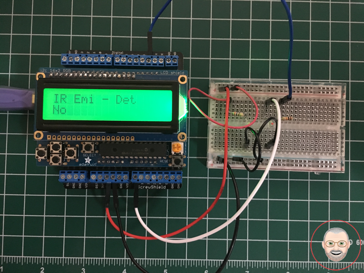
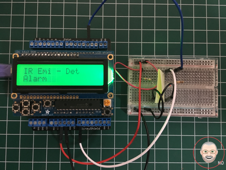
DonLuc1807Mk08p.ino
// ***** Don Luc *****
// Software Version Information
// Project #7: RGB LCD Shield – IR Emitters and Detectors – Mk04
// 7-8
// DonLuc1807Mk08p 7-8
// RGB LCD Shield
// IR Emitters and Detectors

// include the library code:
#include <Adafruit_MCP23017.h>
#include <Adafruit_RGBLCDShield.h>

Adafruit_RGBLCDShield RGBLCDShield = Adafruit_RGBLCDShield();
#define GREEN 0x2

// IR Emitters and Detectors
int iDet = 2;
int iSense = A0;
int iVal;

void loop()
{

  // Display
  // Set the cursor to column 0, line 0
  RGBLCDShield.setCursor(0,0);
  RGBLCDShield.print("IR Emi - Det");     // IR Emitters and Detectors

  // IR Emitters and Detectors
  iVal = analogRead(iSense);

  // Set the cursor to column 0, line 1
  RGBLCDShield.setCursor(0, 1);
  if ( iVal >= 1005 )
  {
     RGBLCDShield.print("Alarm");         // Alarm
  }
  else
  {
     RGBLCDShield.print("No");            // No
  }

  delay(1000);

  // Clear
  RGBLCDShield.clear();

}
setup.ino
// Setup
void setup()
{

  // set up the LCD's number of columns and rows:
  RGBLCDShield.begin(16, 2);
  RGBLCDShield.setBacklight(GREEN);

  // Display
  // Set the cursor to column 0, line 0
  RGBLCDShield.setCursor(0,0);
  RGBLCDShield.print("Don Luc");         // Don luc
  // Set the cursor to column 0, line 1
  RGBLCDShield.setCursor(0, 1);
  RGBLCDShield.print("IR Emi - Det");    // IR Emitters and Detectors

  delay(5000);

  // Clear
  RGBLCDShield.clear();

  // IR Emitters and Detectors
  pinMode(iDet, OUTPUT);
  pinMode(iSense, INPUT);
  digitalWrite(iDet,HIGH);

}
Don Luc
Project #9: Stepper – EasyDriver – Mk04
EasyDriver – Hook-Up
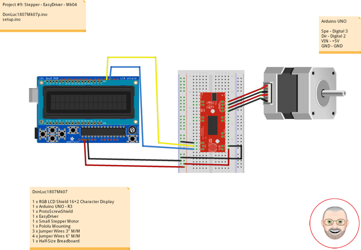
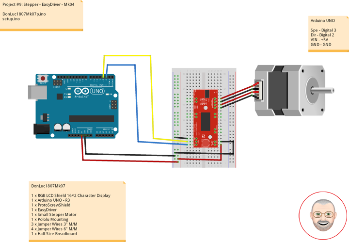
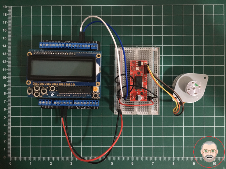
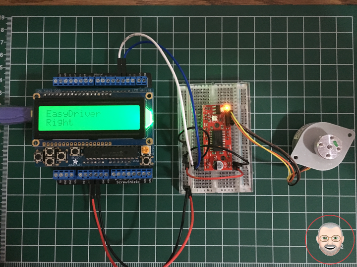
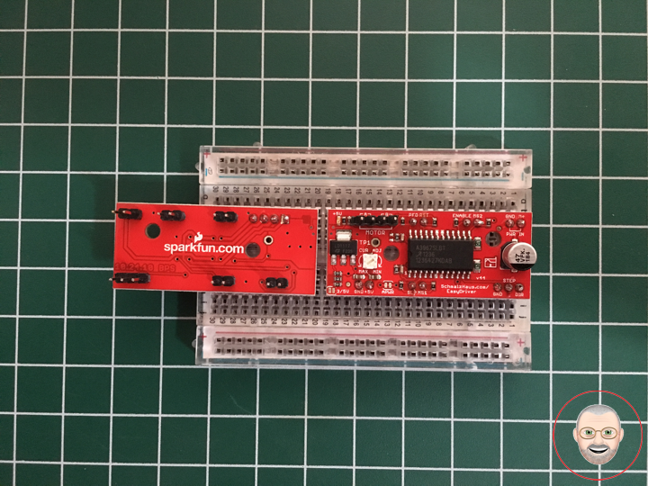
Once you have all the headers soldered on, it’s time to hook up the EasyDriver to your Arduino. Using the picture below, make all the necessary connections.
Note: The small stepper motor looks different than the one pictured. It should have a 4-pin connector on the end. This will be attached to the 4-pin male header facing upward. Because of the nature of this particular stepper, you can hook up the connector in either orientation, i.e. either the black wire on the left or the yellow wire on the left. It will work either way. If you are using a different motor, consult its documentation to find out which wires should go where.
IMPORTANT: Stepper motors require more power than can be supplied by the Arduino. In this example we will be powering the Uno with a 12V external supply. Notice that the power input (M+) on the EasyDriver is attached to the Vin pin on the Arduino. This will allow you to power both the Arduino and the motor with the same power supply.
DonLuc1807Mk07
1 x RGB LCD Shield 16×2 Character Display
1 x Arduino UNO – R3
1 x ProtoScrewShield
1 x EasyDriver
1 x Small Stepper Motor
1 x Pololu Mounting
3 x Jumper Wires 3″ M/M
4 x Jumper Wires 6″ M/M
1 x Half-Size Breadboard
Arduino UNO
Spe – Digital 3
Dir – Digital 2
VIN – +5V
GND – GND
DonLuc1807Mk07p.ino
// ***** Don Luc *****
// Software Version Information
// Project #9: Stepper - EasyDriver - Mk04
// 7-7
// DonLuc1807Mk07p 7-7
// Stepper
// EasyDriver

// include the library code:
#include <Adafruit_MCP23017.h>
#include <Adafruit_RGBLCDShield.h>

Adafruit_RGBLCDShield RGBLCDShield = Adafruit_RGBLCDShield();
#define GREEN 0x2

// EasyDriver
int dirPin = 2;                           // EasyDriver
int stepPin = 3;                          // stepPin

void loop() {

  // Display
  // Set the cursor to column 0, line 0
  RGBLCDShield.setCursor(0,0);
  RGBLCDShield.print("EasyDriver");       // EasyDriver

  // EasyDriver
  int i;

  // Set the cursor to column 0, line 1
  RGBLCDShield.setCursor(0, 1);
  RGBLCDShield.print("Left");             // Left

  digitalWrite(dirPin, LOW);              // Set the direction.
  delay(100);

  for (i = 0; i<4000; i++)                // Iterate for 4000 microsteps.
  {
    digitalWrite(stepPin, LOW);           // This LOW to HIGH change is what creates the
    digitalWrite(stepPin, HIGH);          // "Rising Edge" so the easydriver knows to when to step.
    delayMicroseconds(500);               // This delay time is close to top speed for this
  }                                       // particular motor. Any faster the motor stalls.

  // Set the cursor to column 0, line 1
  RGBLCDShield.setCursor(0, 1);
  RGBLCDShield.print("Right");            // Right

  digitalWrite(dirPin, HIGH);             // Change direction.
  delay(2000);

  for (i = 0; i<4000; i++)                // Iterate for 4000 microsteps
  {
    digitalWrite(stepPin, LOW);           // This LOW to HIGH change is what creates the
    digitalWrite(stepPin, HIGH);          // "Rising Edge" so the easydriver knows to when to step.
    delayMicroseconds(500);               // This delay time is close to top speed for this
  }                                       // particular motor. Any faster the motor stalls.

  delay(2000);

  // Clear
  RGBLCDShield.clear();

}
setup.ino
// Setup
void setup() {

  // set up the LCD's number of columns and rows:
  RGBLCDShield.begin(16, 2);
  RGBLCDShield.setBacklight(GREEN);

  // Display
  // Set the cursor to column 0, line 0
  RGBLCDShield.setCursor(0,0);
  RGBLCDShield.print("Don Luc");         // Don luc
  // Set the cursor to column 0, line 1
  RGBLCDShield.setCursor(0, 1);
  RGBLCDShield.print("EasyDriver");      // EasyDriver

  delay(5000);

  // Clear
  RGBLCDShield.clear();

  // EasyDriver
  pinMode(dirPin, OUTPUT);
  pinMode(stepPin, OUTPUT);

}
Don Luc
Project #9: Stepper – EasyDriver – Mk03
Assembly
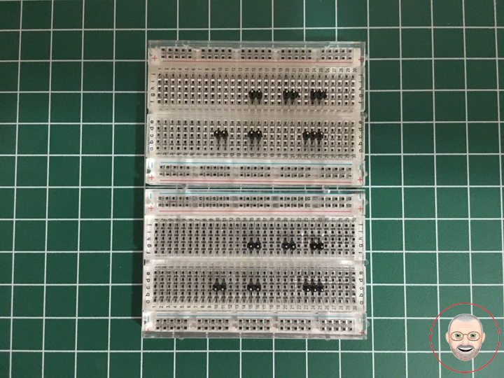
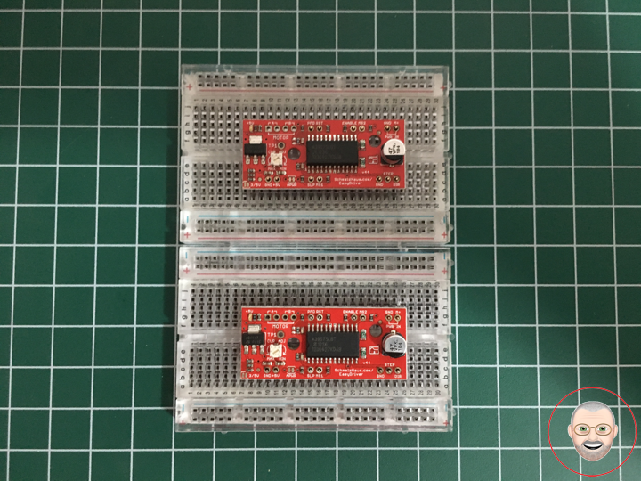
The simplest way to use the EasyDriver is to attach headers to it for easy insertion onto a breadboard. Alternatively, you could solder the wires straight to the board. These instructions will assume you are using the breadboard method.
The first step is to solder straight male headers to the EasyDriver. Very few of the actual pins on the EasyDriver will be used in this example. However, soldering headers on all the broken out pins is recommended to give the board more stability when attached to a breadboard. A simple method for this is to break off the desired amount of headers, place them in the breadboard in the appropriate locations, place the EasyDriver on top, and then solder all the connections.
DonLuc1807Mk06
2 x EasyDriver
10 x 2 Header
2 x 3 Header
2 x 4 Header
2 x Half-Size Breadboard
1 x Flux-Core Solder 60/40
1 x Fume Extractor TENMA
1 x Soldering Station TENMA
Don Luc
Project #9: Stepper – EasyDriver – Mk02
EasyDriver – Stepper Motor Driver
Description
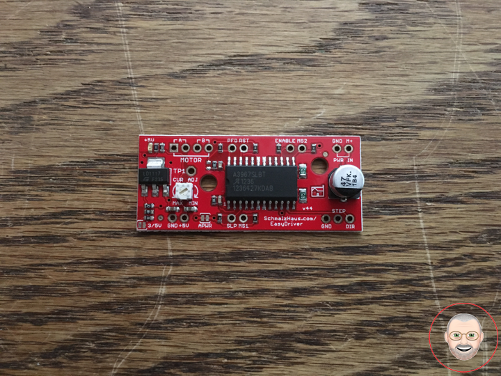
The EasyDriver is a simple to use stepper motor driver, compatible with anything that can output a digital 0 to 5V pulse (or 0 to 3.3V pulse if you solder SJ2 closed on the EasyDriver). The EasyDriver requires a 6V to 30V supply to power the motor and can power any voltage of stepper motor. The EasyDriver has an on board voltage regulator for the digital interface that can be set to 5V or 3.3V. Connect a 4-wire stepper motor and a microcontroller and you’ve got precision motor control! EasyDriver drives bi-polar motors, and motors wired as bi-polar. I.e. 4,6, or 8 wire stepper motors.
This EasyDriver V4.5 has been co-designed with Brian Schmalz. It provides much more flexibility and control over your stepper motor, when compared to older versions. The microstep select (MS1 and MS2) pins of the A3967 are broken out allowing adjustments to the microstepping resolution. The sleep and enable pins are also broken out for further control.
Note: Do not connect or disconnect a motor while the driver is energized. This will cause permanent damage to the A3967 IC.
Note: This product is a collaboration with Brian Schmalz. A portion of each sales goes back to them for product support and continued development.
Features
* A3967 Microstepping Driver
* MS1 and MS2 pins broken out to change microstepping resolution to full, half, quarter and eighth steps (defaults to eighth)
* Compatible with 4, 6, and 8 wire stepper motors of any voltage
* Adjustable current control from 150mA/phase to 700mA/phase
* Power supply range from 6V to 30V. The higher the voltage, the higher the torque at high speeds
Don Luc
Project #9: Stepper – Mk01
Stepper Motor
A stepper motor or step motor or stepping motor is a brushless DC electric motor that divides a full rotation into a number of equal steps. The motor’s position can then be commanded to move and hold at one of these steps without any position sensor for feedback (an open-loop controller), as long as the motor is carefully sized to the application in respect to torque and speed.
Switched reluctance motors are very large stepping motors with a reduced pole count, and generally are closed-loop commutated.
Fundamentals of Operation
Brushed DC motors rotate continuously when DC voltage is applied to their terminals. The stepper motor is known by its property to convert a train of input pulses (typically square wave pulses) into a precisely defined increment in the shaft position. Each pulse moves the shaft through a fixed angle.
Stepper motors effectively have multiple “toothed” electromagnets arranged around a central gear-shaped piece of iron. The electromagnets are energized by an external driver circuit or a micro controller. To make the motor shaft turn, first, one electromagnet is given power, which magnetically attracts the gear’s teeth. When the gear’s teeth are aligned to the first electromagnet, they are slightly offset from the next electromagnet. This means that when the next electromagnet is turned on and the first is turned off, the gear rotates slightly to align with the next one. From there the process is repeated. Each of those rotations is called a “step”, with an integer number of steps making a full rotation. In that way, the motor can be turned by a precise angle.
Unipolar Motors
A unipolar stepper motor has one winding with center tap per phase. Each section of windings is switched on for each direction of magnetic field. Since in this arrangement a magnetic pole can be reversed without switching the direction of current, the commutation circuit can be made very simple (e.g., a single transistor) for each winding. Typically, given a phase, the center tap of each winding is made common: giving three leads per phase and six leads for a typical two phase motor. Often, these two phase commons are internally joined, so the motor has only five leads.
Bipolar Motors
Bipolar motors have a single winding per phase. The current in a winding needs to be reversed in order to reverse a magnetic pole, so the driving circuit must be more complicated, typically with an H-bridge arrangement (however there are several off-the-shelf driver chips available to make this a simple affair). There are two leads per phase, none are common.
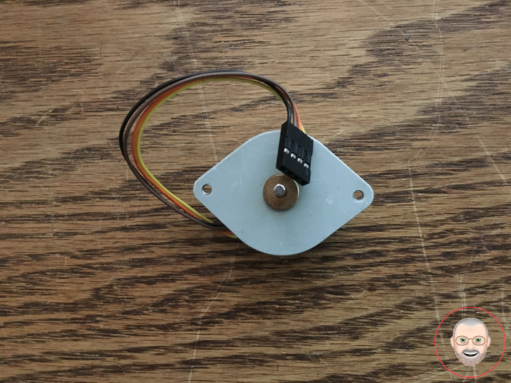
Small Stepper Motor
Description
These small steppers are a great way to get things moving, especially when positioning and repeatability is a concern.
When using a current limiting driver such as the Easydriver or Big Easydriver, a 12 volt power supply can be used as long as you adjust the current level to 400mA or less. If using a non current limited driver (like a L293D or an H-bridge) you will need to lower your input voltage to keep the motor current below 400mA.
This is a bipolar motor.
Features
* Stride Angle (degrees): 7.5
* 2-Phase
* Rated Voltage: 12V
* Rated Current: 400mA
* 3mm Diameter Drive Shaft
* 4-Wire Cable Attached
* In-traction Torque: 100 g/cm
Don Luc
Project #8: Servo – Potentiometer Servo – Mk01
Servo Motor
A servo motor is a rotary actuator or linear actuator that allows for precise control of angular or linear position, velocity and acceleration. It consists of a suitable motor coupled to a sensor for position feedback. It also requires a relatively sophisticated controller, often a dedicated module designed specifically for use with servo motors.
Servo motors have been around for a long time and are utilized in many applications. They are small in size but pack a big punch and are very energy-efficient. These features allow them to be used to operate remote-controlled or radio-controlled toy cars, robots and airplanes. Servo motors are also used in industrial applications, robotics, in-line manufacturing, pharmaceutics and food services.
Circuit
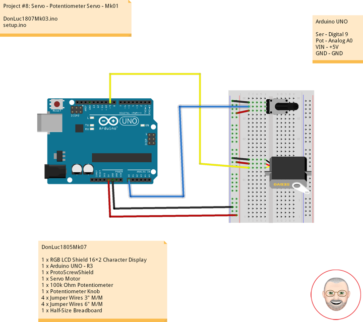
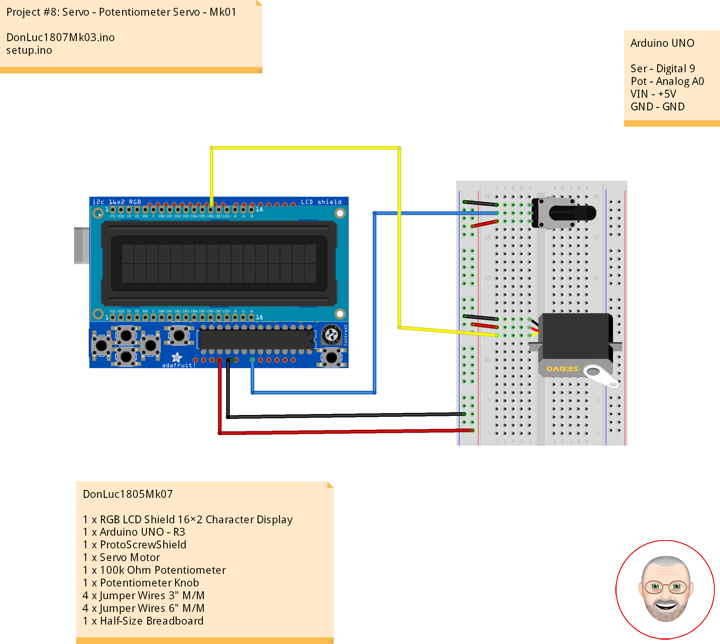
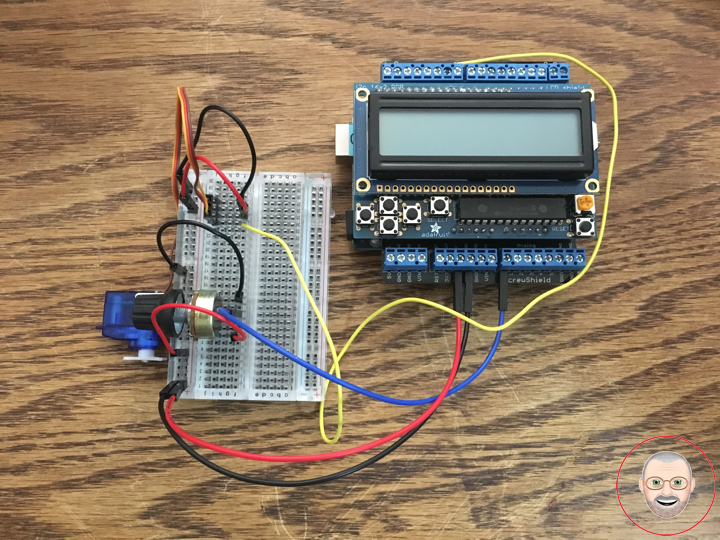
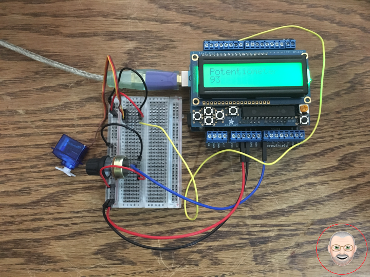
Servo motors have three wires: power, ground, and signal. The power wire is red, and should be connected to the 5V pin on the Arduino board. The ground wire is black and should be connected to a ground pin on the board. The signal pin is orange and should be connected to pin 9 on the board.
The potentiometer should be wired so that its two outer pins are connected to power (+5V) and ground, and its middle pin is connected to analog input 0 on the board.
DonLuc1805Mk07
1 x RGB LCD Shield 16×2 Character Display
1 x Arduino UNO – R3
1 x ProtoScrewShield
1 x Servo Motor
1 x 100k Ohm Potentiometer
1 x Potentiometer Knob
4 x Jumper Wires 3″ M/M
4 x Jumper Wires 6″ M/M
1 x Half-Size Breadboard
Arduino UNO
Ser – Digital 9
Pot – Analog A0
VIN – +5V
GND – GND
DonLuc1807Mk03.ino
// ***** Don Luc *****
// Software Version Information
// Project #8: Servo Motor - Potentiometer - Mk01
// 7-3
// DonLuc1807Mk03 7-3
// Servo Motor
// Potentiometer Servo

// include the library code:
#include <Adafruit_MCP23017.h>
#include <Adafruit_RGBLCDShield.h>
#include <Servo.h>

Adafruit_RGBLCDShield RGBLCDShield = Adafruit_RGBLCDShield();
#define GREEN 0x2

// Potentiometer Servo Motor
Servo isServo;                            // Create servo object to control a servo
int iPot1 = A0;                           // Analog Potentiometer 1
int iVal;                                 // Variable - Analog Potentiometer 1

void loop() {

  // Potentiometer Servo Motor
  iVal = analogRead(iPot1);               // Reads the value of the iPot1 (Value between 0 and 1023)
  iVal = map(iVal, 0, 1023, 0, 180);      // Scale it to use it with the isServo (Value between 0 and 180)
  isServo.write(iVal);                    // isServo sets the servo position according to the scaled value
  delay(15);

  // Display
  // Set the cursor to column 0, line 0
  RGBLCDShield.setCursor(0,0);
  RGBLCDShield.print("Potentiometer");     // Potentiometer
  // Set the cursor to column 0, line 1
  RGBLCDShield.setCursor(0, 1);
  RGBLCDShield.print(iVal);                // Reads the value iVal

  delay(500);

  // Clear
  RGBLCDShield.clear();

}
setup.ino
// Setup
void setup() {

  // set up the LCD's number of columns and rows:
  RGBLCDShield.begin(16, 2);
  RGBLCDShield.setBacklight(GREEN);

  // Display
  // Set the cursor to column 0, line 0
  RGBLCDShield.setCursor(0,0);
  RGBLCDShield.print("Don Luc");         // Don luc
  // Set the cursor to column 0, line 1
  RGBLCDShield.setCursor(0, 1);
  RGBLCDShield.print("Potentiometer");   // Potentiometer Servo Motor

  delay(5000);

  // Clear
  RGBLCDShield.clear();

  // Potentiometer Servo Motor
  isServo.attach(9);                     // Attaches the Servo on pin 9 to the Servo Object

}
Don Luc
